Time to failure analysis of robotic arm cabling

a technology of robotic arm and time to failure analysis, applied in the field of life prediction apparatuses, can solve the problems of robot halt, cable fatigue, and inability to establish the life calculation method, and achieve the effect of reducing cost and effor

Active Publication Date: 2021-10-12
FANUC LTD
View PDF27 Cites 0 Cited by
  • Summary
  • Abstract
  • Description
  • Claims
  • Application Information

AI Technical Summary

Benefits of technology

[0007]Thus, an object of the present invention is to provide a life prediction apparatus capable of accurately performing life prediction of a cable wired at joint portions of a robot.
[0010]The present invention eliminates the need for the structure of a detector or the like for predicting the life of a cable, and can thus reduce cost and effort.

Problems solved by technology

These cables become fatigued by being bent or twisted with operation of each joint of the robot.
With the progress of fatigue, a trouble such as a break occurs in a cable, which may lead to a halt of the robot.
On the other hand, as for life prediction of a cable wired in a robot, its life calculation method has not been established.
However, in the above-described prior art techniques of detecting an abnormality of the cable, a device for detecting a break in a cable, a device for measuring a resistance value, or the like is required, thereby posing a problem of incurring cost and effort.
Moreover, even if the above-described technology of predicting a life of a component of a robot is applied to a cable, methodologies as to how the life of the cable can be appropriately predicted have not been established, and it is difficult to simply use the above-described techniques for cable life prediction.

Method used


Image

  • Time to failure analysis of robotic arm cabling
  • Time to failure analysis of robotic arm cabling
  • Time to failure analysis of robotic arm cabling

Examples


first embodiment

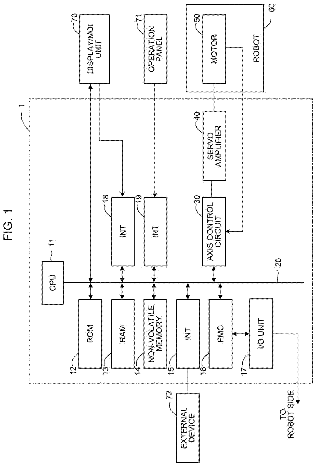
[0021]FIG. 1 is a schematic diagram of hardware structure of main parts of a life prediction apparatus according to the present invention. A life prediction apparatus 1 of the present invention can be implemented as, for example, a controller for a robot 60. The life prediction apparatus 1 of the present invention can also be implemented as, for example, a host computer, cell computer, cloud server, or the like connected to a controller of the robot 60 via a network or the like.

[0022]The life prediction apparatus 1 according to the present embodiment includes a CPU 11, which is a processor for generally controlling the life prediction apparatus 1. The CPU 11 reads a system program stored in a ROM 12 via a bus 20 to control the entire life prediction apparatus 1 in accordance with the system program. In a RAM 13, temporary computation data, display data, various data inputted by an operator via a display / MDI unit 70, which will be described further below, and so forth are stored.

[002...

second embodiment

[0046]FIG. 6 is a schematic diagram of hardware structure of main parts of a life prediction apparatus according to the present invention. The life prediction apparatus 1 of the present embodiment can be implemented as, for example, a host computer, cell computer, cloud server, or the like connected to controllers of a plurality of robots 60 of the same type via a network or the like. The basic function of each of the CPU 11, the ROM 12, the RAM 13, and the non-volatile memory 14, which are provided in the life prediction apparatus 1, is similar to that described with reference to FIG. 1.

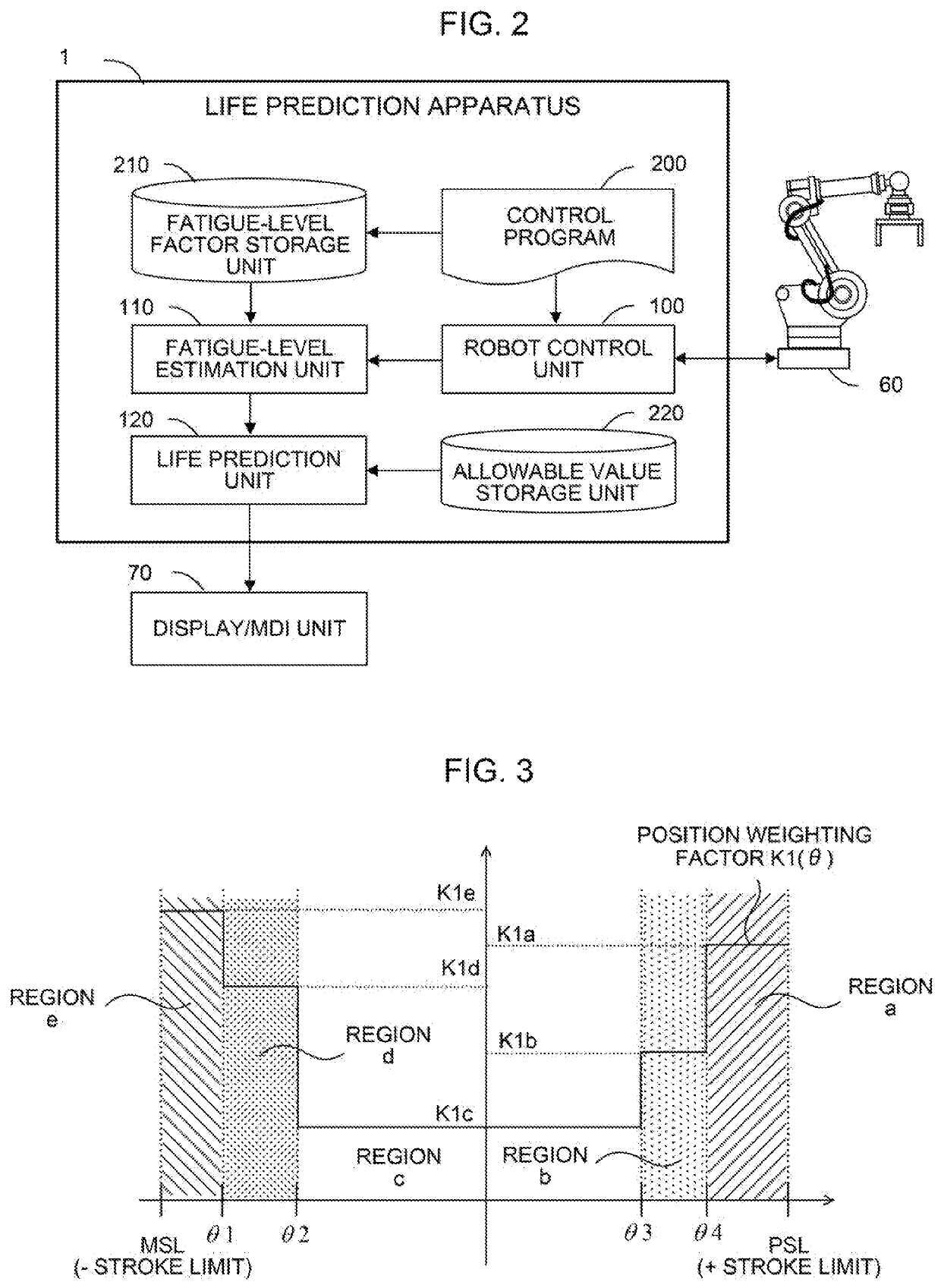
[0047]The life prediction apparatus 1 according to the present embodiment has a function of receiving, via an interface 22, data collected from a controller of each robot 60 connected via a network and estimating the position weighting factor K1(θ) and the allowable value C of the cable based on the received data. The life prediction apparatus 1 includes a machine learning apparatus 300 which estima...


PUM


Abstract

A life prediction apparatus is configured to accurately predict a life of a cable wired at a joint part of a robot. The life prediction apparatus includes a fatigue-level estimation unit for estimating a fatigue level of the cable based on encoder information of an actuator which moves the joint part of the robot, and a life prediction unit for predicting the life of the cable based on a fatigue level of the cable estimated by the fatigue-level estimation unit and an allowable value of the cable.

Description

CROSS-REFERENCE TO RELATED APPLICATION[0001]This application is a new U.S. Patent Application that claims benefit of Japanese Patent Application No 2017-209166, filed Oct. 30, 2017, the disclosure of this application is being incorporated herein by reference in its entirety for all purposes.BACKGROUND OF THE INVENTION1. Field of the Invention[0002]The present invention relates to life prediction apparatuses and, in particular, to a life prediction apparatus which predicts the life of a cable wired at joint parts of a robot.2. Description of the Related Art[0003]In an articulated robot, as depicted in FIG. 8, it is required to wire a motor cable for moving each joint, a cable for driving a device attached to the robot, a signal cable to an encoder, and so forth over joint parts. These cables become fatigued by being bent or twisted with operation of each joint of the robot. With the progress of fatigue, a trouble such as a break occurs in a cable, which may lead to a halt of the robo...

Claims


Application Information

Patent Timeline
Patent Type & Authority Patents(United States)
IPC IPC(8): G05B19/4065B25J9/16B25J19/00G01R31/58B25J13/06B25J19/06G05B13/04G05B23/02
CPCG05B19/4065B25J9/1674B25J13/06B25J19/0025B25J19/0095B25J19/06G01R31/58G05B13/048G05B23/0283G05B2219/37254
Inventor TANNO, YOSHIHIROOIKAWA, AKIHIROOHASHI, TOSHINORI
Owner FANUC LTD
Why Eureka
Try Eureka