Single shot X-ray phase-contrast and dark field imaging

a phase-contrast and single-shot technology, applied in the field of single-shot x-ray phase-contrast and dark field imaging, can solve the problems of difficult acquisition, cumbersome image acquisition procedure, and significant increase in image acquisition time, and achieve the effect of improving noise robustness

Active Publication Date: 2021-10-26
KONINKLJIJKE PHILIPS NV
View PDF16 Cites 2 Cited by
  • Summary
  • Abstract
  • Description
  • Claims
  • Application Information

AI Technical Summary

Benefits of technology

[0013]The regions of different phases (or phase regions) as proposed herein define a spatial structuring of the radiation sensitive component, in particular one or more of its layers. The structuring is such that underlying detector pixels can simultaneously capture intensities as seen through the periodic structures of different phases. This allows efficient signal processing of the captured intensities into phase-contrast- and / or dark-field- and / or transmission imagery.
[0015]The proposed structuring into multi-phase regions integrated in the detector is capable of affording the following advantages for tomographic or radiography imaging. For radiographic imaging, the proposed structured X-ray component allows limiting cross-talk of the pixels to significantly improve the image noise quality for X-ray phase-contrast and dark-field modality. This is achieved because the structured pixilated X-ray component of the detector allows single exposure acquisitions thanks to regions whose periodicities are at different phases. In tomographic imaging, the proposed component allows more robust data acquisition, in particular when combined with IBSIR (intensity based iterative reconstruction), such as disclosed in the paper by M. von Teuffenbach at el as referenced above. In particular, an angular phase stepping of a sliding window acquisition can be complementing with a spatial phase stepping across adjacent pixels thanks to the proposed X-ray component.

Problems solved by technology

However, this makes image acquisition a cumbersome procedure and significantly increases image acquisition time.
X-ray phase-contrast and dark-field imaging in tomography setting presents also with challenges.
In particular, it is the rotational motion in tomographic acquisitions that makes the acquisition challenging.
However, even in these schemes, some phase stepping is still needed during the acquisition which is at the expense of noise robustness.

Method used


Image

  • Single shot X-ray phase-contrast and dark field imaging
  • Single shot X-ray phase-contrast and dark field imaging
  • Single shot X-ray phase-contrast and dark field imaging

Examples


Embodiment Construction

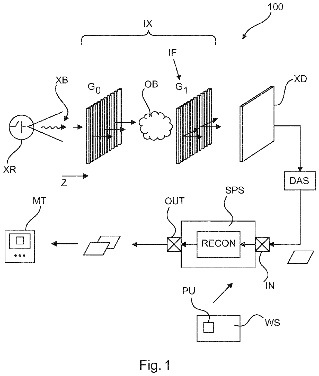
[0032]With reference to FIG. 1 there is shown an imaging arrangement 100 comprising an X-ray imaging apparatus IX capable of producing imagery of an object OB. The X-ray imaging apparatus IX comprises an X-ray source XR and an X-ray sensitive detector XD. There is an examination region between the X-ray source XR and the X-ray detector XD in which resides the object OB to be imaged (or a part thereof).

[0033]The X-ray imager XI envisaged herein is primarily envisaged for medical applications such as diagnostic or navigation purposes in interventions but other, non-medical applications are not excluded herein. In other words, the object OB may be animate such as a human or animal patient or a part thereof (such as an anatomy of interest), or the object OB may be inanimate such as in security package screenings or non-destructive material testing, or other.

[0034]The optical axis and propagation direction of the imaging apparatus IX is indicated by Z in the Figure. The optical axis defi...


PUM

PropertyMeasurementUnit
periodic structuresaaaaaaaaaa
imagingaaaaaaaaaa
phase contrastaaaaaaaaaa

Abstract

A component (XS) for an X-ray detector device (XD), comprising a layer (SL) tessellated in a plurality of different regions (Rj), the regions having respective periodic structures at a respective phase, wherein two neighboring regions have periodic structures at different phases.

Description

FIELD OF THE INVENTION[0001]The invention relates to a signal processing system, to a signal processing method, to an imaging arrangement, to a computer program product, and to a computer readable medium.BACKGROUND OF THE INVENTION[0002]For radiography acquisitions of X-ray phase-contrast and dark-field imaging with a grating interferometer, a sequence of images is necessary that is acquired with different relative grating positions as proposed by F. Pfeiffer et al, “Hard-X-ray dark-field imaging using a grating interferometer”, in “Nature materials”, vol 7, pp 134-137, February 2008. This makes it necessary to move at least one of the gratings during the image acquisition. However, this makes image acquisition a cumbersome procedure and significantly increases image acquisition time.[0003]X-ray phase-contrast and dark-field imaging in tomography setting presents also with challenges. In particular, it is the rotational motion in tomographic acquisitions that makes the acquisition c...

Claims


Application Information

Patent Timeline
Patent Type & Authority Patents(United States)
IPC IPC(8): A61B6/00G01N23/041G01N23/083G01T1/20G01T1/202G01T1/24
CPCA61B6/484A61B6/4291G01N23/041G01N23/083G01T1/202G01T1/2018G01T1/24G01N2223/04G01N2223/40G01N2223/505
Inventor YAROSHENKO, ANDRIYKOEHLER, THOMAS
Owner KONINKLJIJKE PHILIPS NV
Why Eureka
Try Eureka