
Multi-focal plane head-up display

Active Publication Date: 2021-11-09
E LEAD ELECTRONICS
View PDF29 Cites 2 Cited by
  • Summary
  • Abstract
  • Description
  • Claims
  • Application Information

AI Technical Summary

Benefits of technology

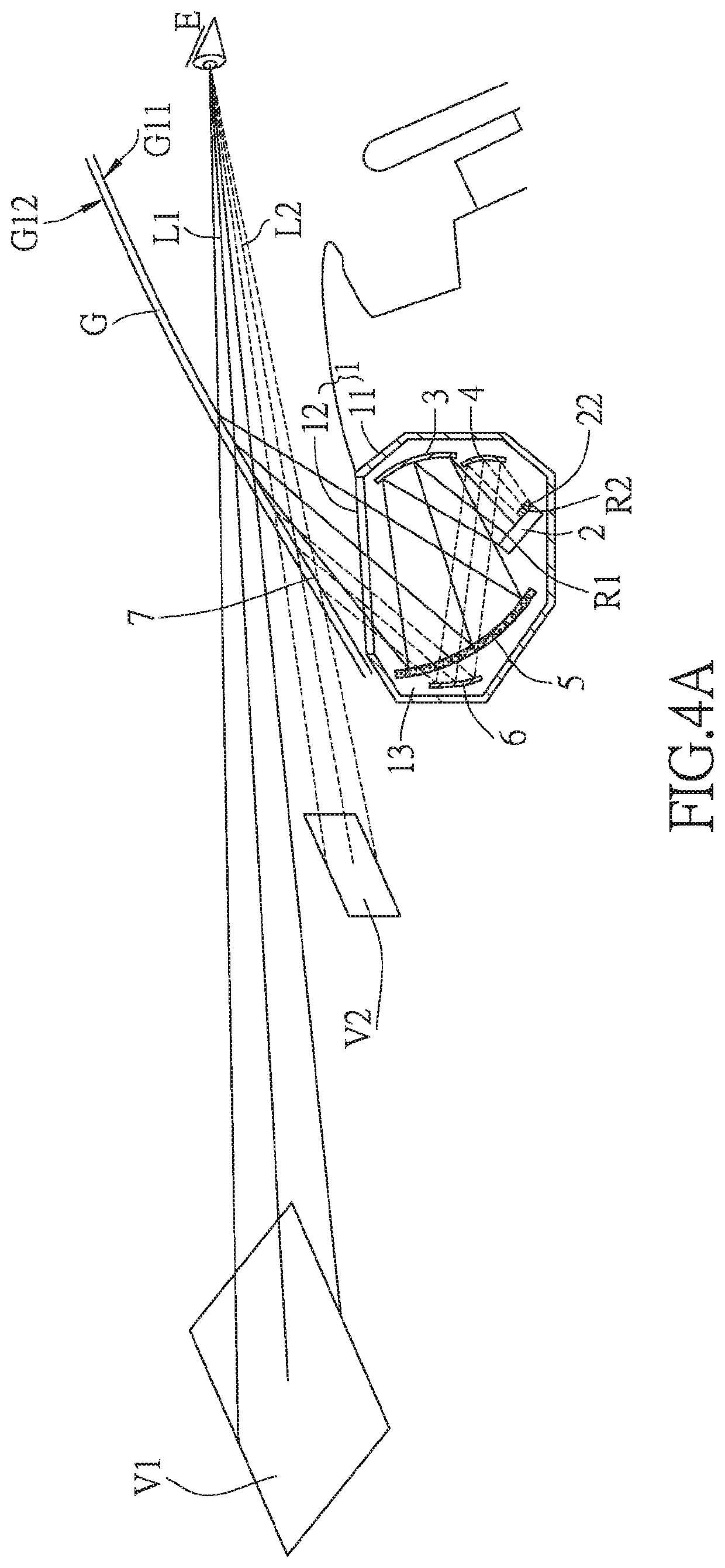
The present invention provides a head-up display that can create multiple virtual images with different focal planes. This is achieved by projecting image lights with different polarization directions from two areas of the projector and designing the optical path of the image lights using reflective elements and a reflective polarizing element. The result is a more compact and efficient head-up display.

Problems solved by technology

Under such circumstances, it is easy to affect driving safety.
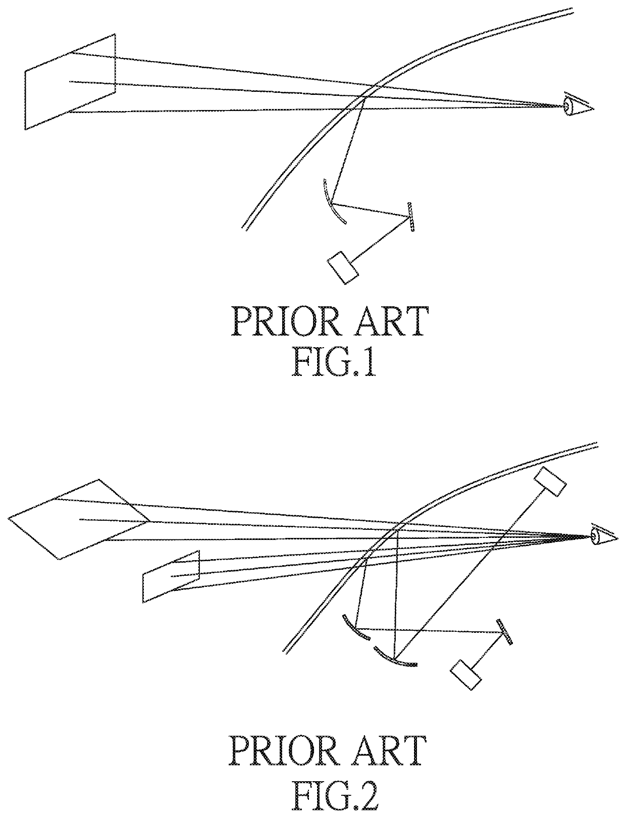
However, when such a head-up display for navigation is used to guide the driver to switch to the correct lane or to warn the driver for the distance to the front vehicle, the image of the guiding sign formed cannot nestle to the road that the driver sees, so that driver still has to shift his attention from the road to the image projected by the head-up display.
However, using two projectors not only requires more reflectors in cooperation with them, but also increases manufacturing costs and space occupation.
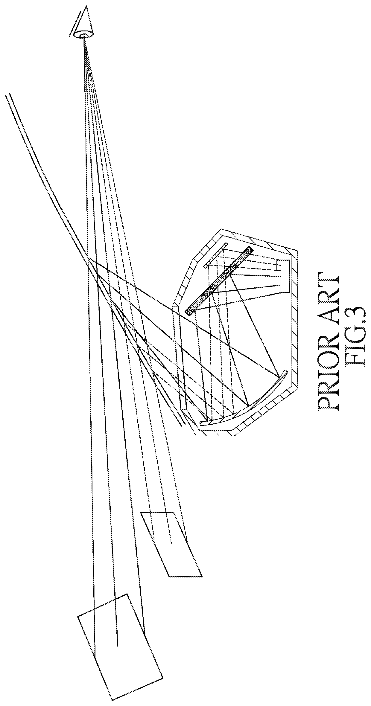
However, in this light path design, the reflective polarizer is likely to obstruct the light outlet, resulting in an insufficient light outlet.

Method used


Image

  • Multi-focal plane head-up display
  • Multi-focal plane head-up display
  • Multi-focal plane head-up display

Examples


Embodiment Construction

[0035]The present invention will be clearer from the following description when viewed together with the accompanying drawings, which show, for purpose of illustrations only, the preferred embodiment in accordance with the present invention.

[0036]Please refer to FIGS. 4A to 5B, a multi-focal plane head-up display provided by an embodiment of the present invention is suitable for installation on a transportation device, such as a vehicle, an airplane, and the like. Specifically, the head-up display of the present invention can be, for example, but not limited to, mounted to a first side G11 of a windshield G of the transportation device. The first side G11 faces the user, and a second side G12 of the windshield G is opposite to the first side G11 and faces the outside of the transportation device.

[0037]The multi-focal plane head-up display may include a main body 1, and the main body 1 includes a housing 11 and a light outlet 12. The main body 1 is arranged on the first side G11 of t...


PUM


Abstract

A multi-focal plane head-up display includes a main body, a projector, a first reflective element, a second reflective element, a polarizing element and a third reflective element. The polarization direction of a first image light in the first region of the projection image projected by the projector and the polarization direction of a second image light in the second region of the projection image are orthogonal to each other. The first image light passes through the first reflective element and the polarizing element to form a first virtual image. The second image light passes through the second reflective element, the polarizing element and the third reflective element to form a second virtual image. This can not only provide two virtual images with different focal planes, but also reduce the volume occupied by the head-up display and reduce manufacturing costs.

Description

BACKGROUNDField of the Invention[0001]The present invention relates to a display, and more particularly to a multi-focal plane head-up display.Related Prior Art[0002]Nowadays, in addition to the performance of the vehicle, the driver's requirements for the vehicle have begun to focus on the interior and safety equipment of the vehicle. The assistance of technological products, such as an internal voice navigation system, a voice collision warning system, etc., does reduce the occurrence of accidents caused by drivers' long time fatigued driving, distraction, etc. Moreover, the dashboard that the driver must use is a non-voice device, and it is usually set below the driver's eye level, so the driver often needs to move his sight down to the dashboard to see the information provided on the dashboard. In addition, the display device of the navigation system is usually installed on the side of the dashboard. Therefore, when the driver wants to view the road information on the display de...

Claims


Application Information

Patent Timeline
IPC IPC(8): G02B27/01G02B27/00
CPCG02B27/0101G02B27/0093G02B2027/0196G02B27/283G02B2027/0185
Inventor CHEN, STEPHEN
Owner E LEAD ELECTRONICS
Learn More