Multi-spectral whole-slide scanner

a multi-spectral, whole-slide technology, applied in the field of microscopy, can solve problems such as unsatisfactory implementation, and achieve the effects of improving pathological analysis, improving diagnostic significance of spectral resolution, and reducing the number of spectral resolution

Inactive Publication Date: 2011-01-04
DMETRIX INC
View PDF12 Cites 3 Cited by
  • Summary
  • Abstract
  • Description
  • Claims
  • Application Information

AI Technical Summary

Benefits of technology

[0014]In essence, the invention lies in the use of an array microscope that makes it possible to scan a whole sample slide in rapid sequence at different illumination wavelengths to record multiple spectral images of the same sample. As a result of this approach, full spatial resolution of the image sensor is realized at each color because pixels are not shared between spectral bands. The image quality and focus can be optimized separately at each color, instead of relying on conventional chromatic correction, which is not sufficiently perfect when implemented with commercially affordable optical elements, such as those made of plastic materials. Image-sensor response can be carefully calibrated separately for each color.
[0016]Image spectral analysis is carried out by combining the images captured at each wavelength to produce a vector of spectral responses for each detector pixel, thereby yielding spectral information that is not available when broadband illumination is used. On the basis of this information and the corresponding greater spectral resolution, the contemporaneous effects of a larger number of stains on a tissue sample may be isolated and displayed for improved pathological analysis. The summation of spectral images may be weighted in some fashion (such as by using a filter vector with positive and / or negative weights) to further improve the diagnostic significance of the spectral resolution produced by the invention.

Problems solved by technology

The image quality and focus can be optimized separately at each color, instead of relying on conventional chromatic correction, which is not sufficiently perfect when implemented with commercially affordable optical elements, such as those made of plastic materials.

Method used


Image

  • Multi-spectral whole-slide scanner
  • Multi-spectral whole-slide scanner
  • Multi-spectral whole-slide scanner

Examples


Embodiment Construction

[0027]Co-owned International Application PCT / US02 / 08286 and U.S. patent application Ser. No. 10 / 158,626, herein incorporated by reference, describe a new approach to microscopy. An array microscope is disclosed that comprises a plurality of optical imaging elements configured to image respective sections of an object and disposed with respect to an object plane so as to produce at respective image planes respective images of the respective sections of the object measurements. The object may be illuminated in a variety of ways, i.e., by trans-illumination, epi-illumination, or epi-fluorescence, as these terms are understood in the art.

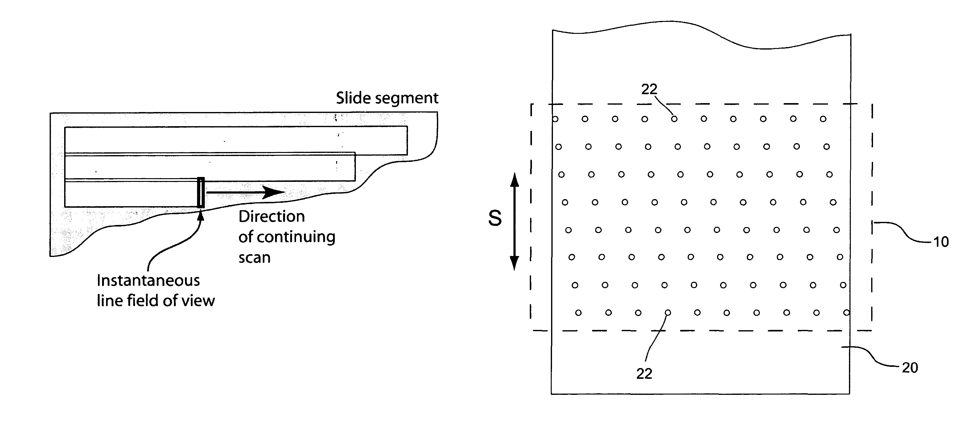
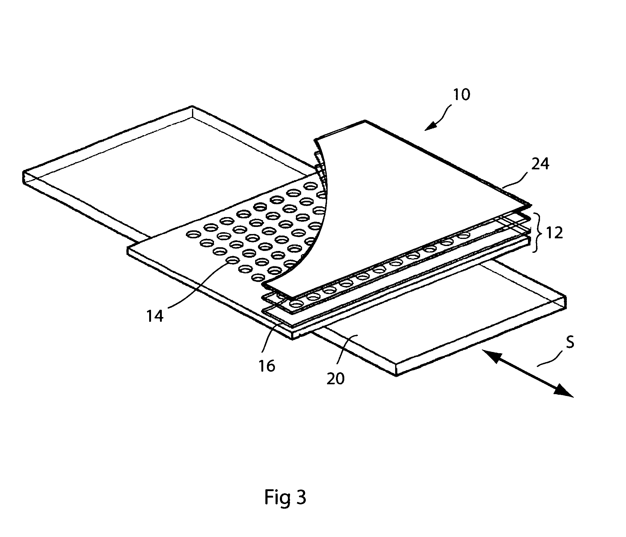
[0028]As illustrated in FIG. 3, the array microscope 10 of Ser. No. 10 / 158,626 consists of a number of lens plates 12, each patterned with individual lenses 14 disposed in staggered rows which, coupled to other correspondingly staggered rows of lenses in parallel plates, form individual optical systems 16. As illustrated by arrow S, the array microscope...


PUM


Abstract

An array microscope scans a slide in rapid sequence at different wavelengths to record multiple spectral images of the sample. Full spatial resolution of the image sensor is realized at each color because pixels are not shared between spectral bands. The object and detector are placed at conjugate distances selected to produce substantially equal magnification with minimum chromatic aberration at all wavelengths to ensure registration of all images. Spectral analysis is carried out by combining the images captured at each wavelength. The greater-than-RGB spectral resolution provided by the combination of images enables the isolation and display of the effects produced by the contemporaneous use of more than two stains on a tissue for improved pathological analysis.

Description

RELATED APPLICATIONS[0001]This application is based on Provisional Application No. 60 / 753,879, filed Dec. 23, 2005, and is a continuation-in-part application of U.S. Ser. No. 10 / 637,486, filed Aug. 11, 2003, which is a continuation application of PCT / US02 / 08286, filed Mar. 19, 2002, and claims the benefit of priority of U.S. Provisional Application No. 60 / 276,498, filed Mar. 19, 2001, under 35 U.S.C. Sect. 119.BACKGROUND OF THE INVENTION[0002]1. Field of the Invention[0003]This invention relates in general to the field of microscopy and, in particular, to a novel approach for providing multi-spectral illumination for pathologic analysis of tissue slides.[0004]2. Description of the Prior Art[0005]Changes in the cellular structure of tissue are used to detect pathologic changes, such as to assess the progress of precancerous conditions and to detect cancer. A tissue sample removed from a patient is typically sectioned and fixed to a slide for staining and microscopic examination by a ...

Claims


Application Information

Patent Timeline
Patent Type & Authority Patents(United States)
IPC IPC(8): G02B6/04H04N1/04
CPCG01J3/02G01J3/0208G01J3/0235G01J3/0237G01J3/10G01J3/2803G01J3/2823G01N21/253G02B21/367G01N21/31
Inventor OLSZAK, ARTUR G.LIANG, CHEN
Owner DMETRIX INC
Why Eureka
Try Eureka