Optofluidic diagnostics system

a technology of optically guided instruments and diagnostics, which is applied in the field of measuring or testing systems and processes, can solve the problems of large sample and reagent requirements, large sample and reagent volumes, and inability to deploy at point-of-care testing and other field applications, and achieve the effect of improving detection performance and amplifying optical properties

Active Publication Date: 2021-11-23
OPTOFLUIDIC BIOASSAY LLC
View PDF21 Cites 0 Cited by
  • Summary
  • Abstract
  • Description
  • Claims
  • Application Information

AI Technical Summary

Benefits of technology

[0007]The flat, or planar, observation face enables improved imaging conditions by establishing a more uniform, more evenly distributed optical color representation of the biochemical molecules resolved during the diagnostic procedure. A flat observation face advantageously spreads color-affected light, thus increasing the efficiency, sensitivity and effectiveness of optical detection. The unique configuration of the optofluidic sensor units thus improves analyte capture efficiency, can reduce assay time which can lead to a more rapid diagnosis, and ultimately facilitates high-throughput screening.
[0009]The test plate of this invention is less bulky by comparison to standard prior art well plates. The test plate can avoid the requirement to add reagents manually. The test plate is beneficial in improving analyte capture efficiency and allows for addition and withdrawal of analytes (solution) by either capillary force or induced pressure differential or a combination of both. The test plate is conducive to use of predefined and prepopulated reagents in the wells and provides efficient means for reagents / analytes delivery and draining. Furthermore, the test plate cooperates with an overall system that can be deployed at bedside of patients, doctors' offices, and in space-limited laboratories.
[0011]The optical detection cartridge makes optical cross-talk preventable among individual optofluidic sensor units, thus enabling improved accuracy in chemiluminescence or fluorescence detection schemes if desired. A optical detection cartridge is effective to increase the efficiency, sensitivity and effectiveness of optical detection, and directly facilitates high-throughput testing procedures.

Problems solved by technology

However, the current ELISA systems are generally ill-suited to deploy at point-of-care testing and other field applications due to such common drawbacks as: long testing time (3-6 hours+overnight coating); large sample and reagent consumption (50-100 μL per sensor well); and the requirement of bulky and expensive microplate readers.
Some prior art systems, such as that proposed in U.S. Pat. No. 8,088,593 assigned to Theranos, Inc. of Palo Alto, Calif., recognize the need for point-of-care diagnostic systems, but have failed to adequately optimize optical detection efficiency and continue to advocate bulky well plate designs.

Method used


Image

  • Optofluidic diagnostics system
  • Optofluidic diagnostics system
  • Optofluidic diagnostics system

Examples


Embodiment Construction

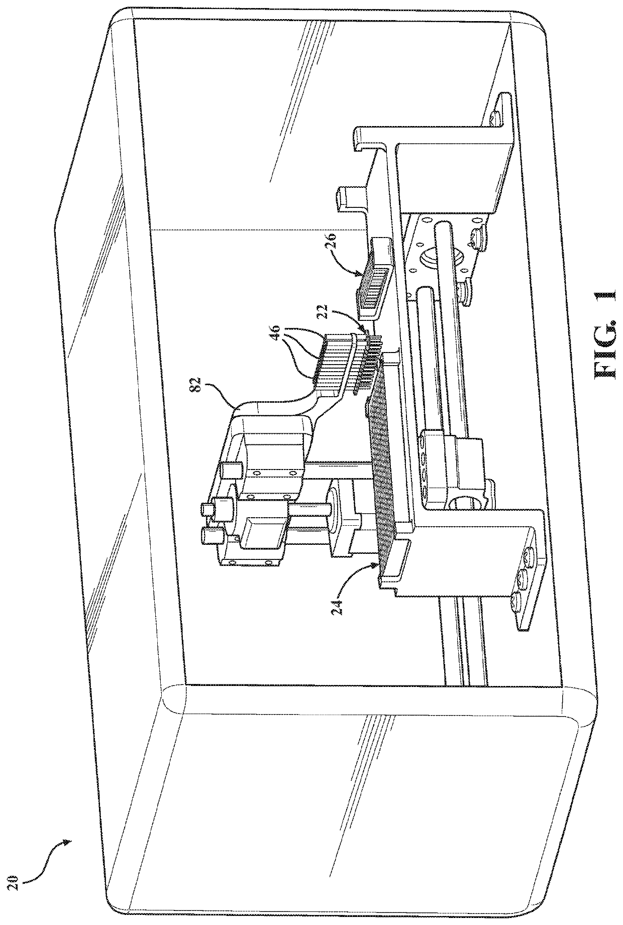
[0029]Referring to the figures, wherein like numerals indicate like or corresponding parts throughout the several views, an optofluidic diagnostic system according to one exemplary embodiment of the invention is generally shown at 20 in FIG. 1. The automated optofluidic diagnostic system 20 is designed for rapid biological and chemical analysis. Its many advantages include using less analyte and reagent solutions than the amount used in traditional protocol. Furthermore, the system 20 is able to perform high-throughput detections because of its capability to automatically load and unload the solutions.

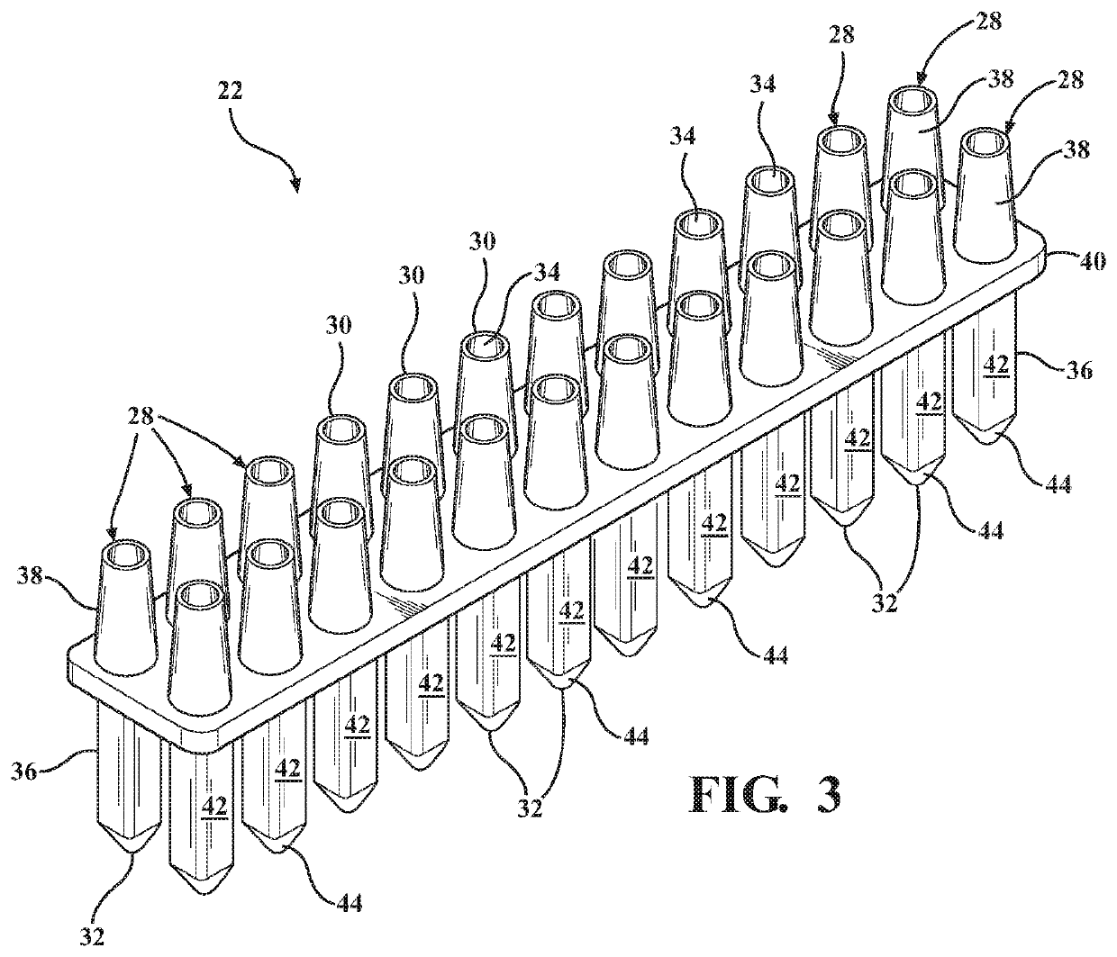
[0030]Generally stated, the optofluidic diagnostic system 20 is composed of three primary parts or modules: a sensor array 22, a test plate 24 and an optical detection cartridge 26. Each module is independent of the other two modules, in the sense that each module is capable of stand-alone use independent of the unique attributes found in the other modules. However, all three of these ...


PUM

PropertyMeasurementUnit
distanceaaaaaaaaaa
internal diameteraaaaaaaaaa

Abstract

An optofluidic diagnostic system and methods for rapid analyte detections. The system comprises an optofluidic sensor array, a test plate and an optical detection cartridge. The sensor array supports one or more distinct sensor units, each having a reactor section designed to temporarily enter a series of different kinds of wells in the test plate. One kind of well is a sample reservoir that holds reagent solution to be transferred into the reactor section. Another kind of well is a drainage chamber that removes reagent solution from the reactor section. A third kind of well is a colorant reservoir that holds a colorant reagent transferable into a reactor section. Finally, the sensor unit is transferred to the optical detection cartridge where it is placed into an isolation booth during the optical detection process so that its flat observation face is stationed in a viewing window opposite an optical detector lens.

Description

CROSS REFERENCE TO RELATED APPLICATIONS[0001]This application claims priority to Provisional Patent Application U.S. 62 / 468,762 filed on Mar. 8, 2017, the entire disclosure of which is hereby incorporated by reference and relied upon.BACKGROUND OF THE INVENTIONField of the Invention[0002]The invention relates generally to measuring or testing systems and processes involving enzymes or microorganisms, and more particularly to improved sensors and well plates and optical detection features therefor.Description of Related Art[0003]Among various diagnostic tests, Enzyme-linked immunosorbent assay (ELISA) has been demonstrated to provide compelling and high performance quantitative and qualitative results. However, the current ELISA systems are generally ill-suited to deploy at point-of-care testing and other field applications due to such common drawbacks as: long testing time (3-6 hours+overnight coating); large sample and reagent consumption (50-100 μL per sensor well); and the requir...

Claims


Application Information

Patent Timeline
Patent Type & Authority Patents(United States)
IPC IPC(8): G01N21/77B01L3/00G01N21/78G01N21/76G01N21/75
CPCG01N21/77B01L3/5085G01N21/78B01L2300/0663B01L2300/0809B01L2300/0829B01L2300/0832B01L2300/0851B01L2300/0858B01L2300/168G01N21/76G01N2021/757G01N2021/7786G01N2201/0446G01N21/253G01N21/6452G01N2021/6482G01N2201/0221
Inventor KHAING OO, MAUNG KYAWFAN, XUDONG
Owner OPTOFLUIDIC BIOASSAY LLC
Why Eureka
Try Eureka