Latch pin for use in valve lifter and valve lifter

a technology for latch pins and lifters, which is applied in the direction of mechanical equipment, machines/engines, engine components, etc., can solve the problems of long response time and variation of latch pins, and achieve the effect of reducing the response time of latch pins, quick deactivation of valves, and improving the response time of switches

Active Publication Date: 2021-11-30
EATON INTELLIGENT POWER LTD
View PDF19 Cites 0 Cited by
  • Summary
  • Abstract
  • Description
  • Claims
  • Application Information

AI Technical Summary

Benefits of technology

[0009]In order to solve the above-mentioned problems, the present invention improves the oil flow around the end of the latch pin by changing the geometric shape of the end of the latch pin.
[0012]A second aspect of the invention relates to a valve lifter, comprising: a cylindrical hollow lifter body; a latch pin as stated above; and a pin housing arranged inside said lifter body and configured to receive the latch pin. Said latch pin is selectively placed in an engagement position or a disengagement position, wherein in the engagement position, the latch pin is engaged within a pin chamber defined in an inner wall surface of said lifter body, thereby preventing relative axial movement between the pin housing and the lifter body, so that axial reciprocating movement of the lifter body causes opening and close of an engine valve via the pin housing; and in the disengagement position, the latch pin is disengaged from the pin chamber, thereby permitting relative axial movement between the pin housing and the lifter body, so that axial reciprocating movement of the lifter body does not cause valve operation via the pin housing.
[0019]According to the present invention, in the engagement position of the latch pin, the rotational movement of the cam of the engine can be transmitted by means of the valve lifter to operate the valve. In particular, the specially designed latch pin according to the invention can be switched to the disengagement position in a short time and thus allow the pin housing to move relative to the lifter body, such that the rotational movement of the engine cam can be interrupted so as to quickly deactivate the valve.
[0020]Therefore, the present invention provides a lifter with improved switch response time, in which the latch pin can be prevented from entering the oil supply hole by means of the modified geometry of the latch pin, thereby reducing the response time of the latch pin.

Problems solved by technology

Such lifters to be used with hydraulic lash adjustment (HLA), however, face the problems that the latch pin's response time (for deactivation) is long and has variation.

Method used


Image

  • Latch pin for use in valve lifter and valve lifter
  • Latch pin for use in valve lifter and valve lifter
  • Latch pin for use in valve lifter and valve lifter

Examples


Embodiment Construction

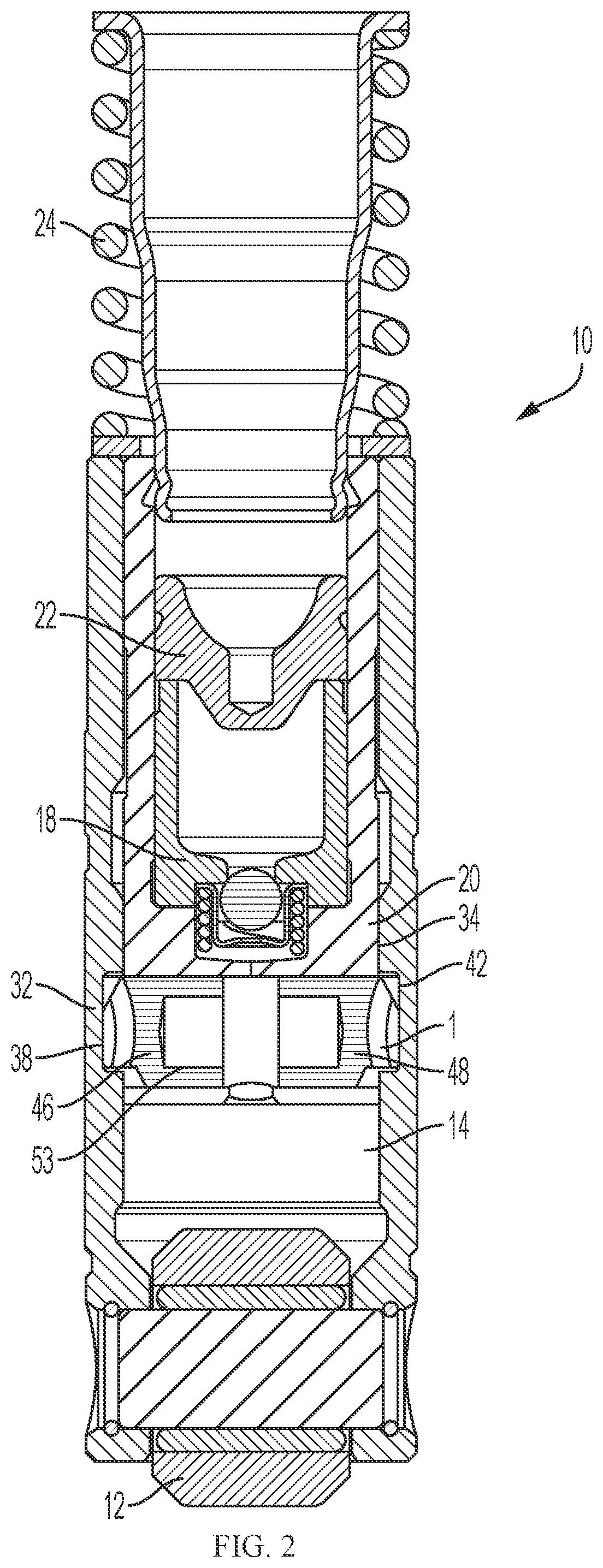
[0027]FIG. 2 shows an embodiment of a hydraulic deactivation lifter (HDL) 10 of the present invention. The HDL 10 includes a roller 12, a lifter body 14, a deactivation pin assembly (latch pin assembly) 1, a plunger assembly 18, a pin housing 20, a pushrod seat assembly 22, and a spring 24.

[0028]The deactivation pin assembly 1 is received within the pin housing 20, which is in turn arranged inside the cylindrical hollow lifter body 14. The deactivation pin assembly 1 is normally placed in an engagement position where it engages with the lifter body 14, thereby transferring the axial reciprocating movement of the lifter body 14 to the pin housing 20 and further to the plunger assembly 18 and pushrod seat assembly 22. In this engagement position, the axial reciprocating movement of HDL 10 opens and closes a valve of the engine.

[0029]When the deactivation pin assembly 1 disengages from the lifter body 14, the lifter body 14 is decoupled from pin housing 20 accordingly and, in turn, the...


PUM


Abstract

Shown is a latch pin for use in a valve lifter and a valve lifter including the same. The latch pin for selectively latching within a pin chamber provided in the valve lifter is configured as a whole as a cylindrical pin with one end in the shape of a spherical crown, wherein a stepped flat is formed on radially one side of said one end and is dimensioned to be received within the pin chamber to engage with an axial latching surface thereof. On the top side of said one end, a first relief is formed by beveling the spherical crown, and on the radially other side opposite to the stepped flat across said first relief, a second relief is formed by beveling the spherical crown, wherein the second relief radially adjoins the first relief and circumferentially adjoins a remaining pin face in the shape of the spherical crown.

Description

PRIORITY[0001]This application claims the benefit of priority of U.S. Provisional Patent Application Ser. No. 62 / 901,147 filed Sep. 16, 2019, which is incorporated by reference herein in its entirety.TECHNICAL FIELD[0002]The present invention relates to a hydraulic valve lifter for use in an engine (e.g. an internal combustion engine), and more particularly to a lifter having an improved latching pin to realize valve deactivation in a push rod engine.BACKGROUND[0003]Valve / cylinder deactivation is the deactivation of the intake and / or exhaust valves of a cylinder or cylinders during at least a portion of the combustion process. Since valve deactivation reduces the number of engine cylinders within which the combustion process is taking place, it is a proven method by which fuel economy can be improved and also the amount of pollutants emitted from the engine can be reduced.[0004]Some known approaches of providing selective valve deactivation in a push rod engine include to equip the ...

Claims


Application Information

Patent Timeline
Patent Type & Authority Patents(United States)
IPC IPC(8): F01L1/24F01L13/00F01L1/46F01L1/245
CPCF01L13/0005F01L1/46F01L2001/2427F01L2001/256F01L1/146F01L2001/467F01L2013/105F01L2305/00
Inventor JENSEN, JASON M.VANCE, MATTHEW A.CORNETT, DOUGLAS R.
Owner EATON INTELLIGENT POWER LTD
Why Eureka
Try Eureka