Oil pump structure of transmission

a technology of oil pump and transmission shaft, which is applied in the direction of piston pump, positive displacement liquid engine, gearing, etc., can solve the problems of increasing fuel consumption rate, affecting the flow rate, and increasing so as to reduce the axial dimension of the outer peripheral portion

Inactive Publication Date: 2007-09-27
JATCO LTD
View PDF8 Cites 4 Cited by
  • Summary
  • Abstract
  • Description
  • Claims
  • Application Information

AI Technical Summary

Benefits of technology

[0011]It is, therefore, in view of the previously-described disadvantages of the prior art, an object of the invention to provide an oil pump structure of a transmission capable of ensuring an adequate fluid

Problems solved by technology

This leads to the problem of the increased flow resistance that impedes the flow of oil flowing through the oil passage after merging.
As a result of this, the fuel consumption rate is increased.
This leads to another problems, such as a fall in hydraulic pressure produced by the pump, and generation of noise.
This leads to another problems, such as the increased number of parts r

Method used


Image

  • Oil pump structure of transmission
  • Oil pump structure of transmission
  • Oil pump structure of transmission

Examples


Embodiment Construction

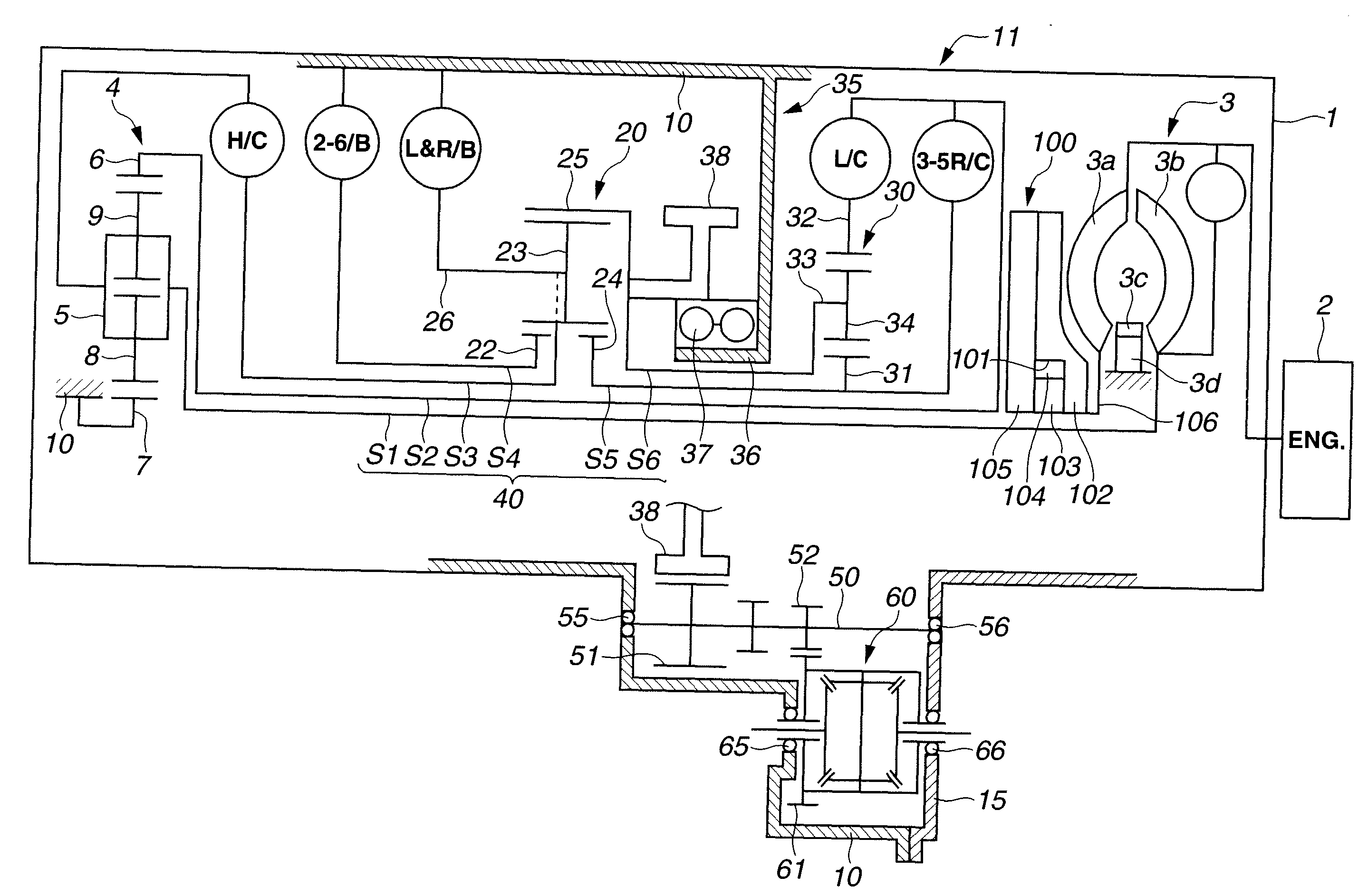
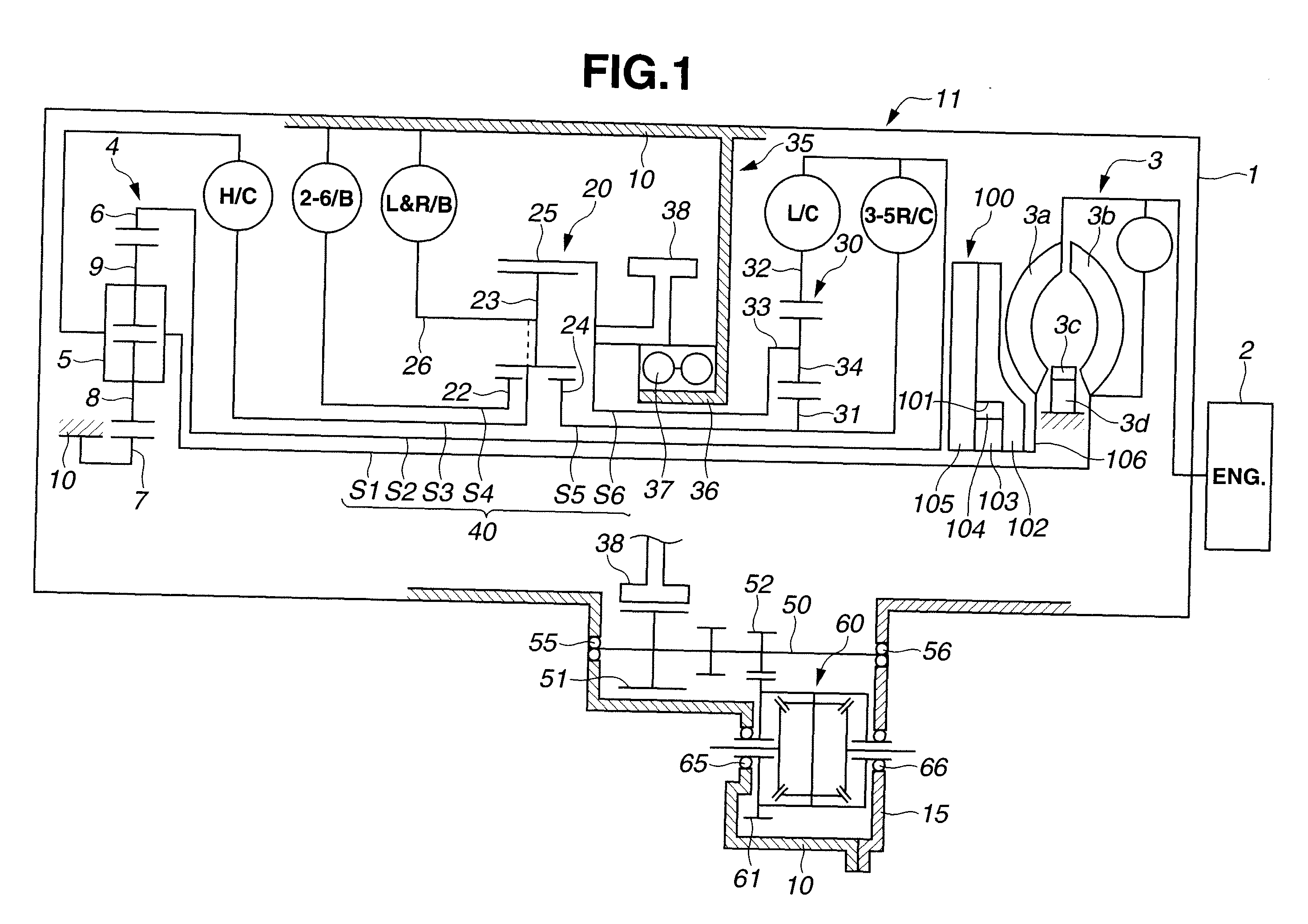
[0022]Referring now to the drawings, particularly to FIG. 1, the oil pump structure of the embodiment is exemplified in an automotive automatic transmission 1, which is comprised of three basic parts, namely a torque converter 3, and planetary-gear systems (described later) included in a transmission mechanism 11. Automatic transmission 1 is connected to an engine 2 and mounted on an automotive vehicle (not shown). Torque converter 3 passes the engine power to the planetary-gear systems.

[0023]Torque converter 3 is comprised of a pump impeller 3a, a turbine runner 3b, a one-way clutch 3d, and a stator 3c. During operation of engine 2, the engine power is transmitted to pump impeller 3a. Turbine runner 3b is located to be opposed to pump impeller 3a for power transmission to a first shaft S1. Stator 3c is located between pump impeller 3a (the driving member) and turbine runner 3b (the driven member). Stator 3c is mounted on one-way clutch 3d, which permits stator 3c to run free when t...


PUM


Abstract

In an oil pump structure of an automatic transmission using a torque converter, a hydraulic pressure chamber is defined by a pump housing and a pump cover, to rotatably accommodate therein inner and outer rotors. First and second inflow ports respectively communicating with an oil strainer and a control valve are formed in the outside surface of the pump cover separately from each other. First and second oil inflow passages communicating with the respective inflow ports, a merged-flow portion that downstream portions of the first and second oil inflow passages are merged with each other, a downstream-side oil distribution channel intercommunicating a downstream side of the merged-flow portion and the hydraulic pressure chamber, are formed in at least one of the pump housing and the pump cover.

Description

TECHNICAL FIELD[0001]The present invention relates to an oil pump structure suitable for an automotive automatic transmission, and specifically to the improvement of a fluid-flow passage structure of an automotive transmission oil pump.BACKGROUND ART[0002]As is generally known, in an automatic transmission mounted on an automotive vehicle, hydraulic pressure used to engage (apply) or disengage (release) each of friction elements, such as clutches and band brakes, and hydraulic pressure used for lubrication of sliding / moving transmission parts with lubricating oil are generated by means of an oil pump. In the automotive automatic transmission, hydraulic pressure has to be generated and supplied by the oil pump, irrespective of whether the vehicle is running or in its stopped state. Thus, in an automatic transmission using a torque converter, an oil pump is laid out in the rear of a torque-converter pump impeller, which is rotated in synchronism with rotation of an engine crankshaft. ...

Claims


Application Information

Patent Timeline
IPC IPC(8): F04B23/00F04B17/00F16H3/44F04C2/10F04C15/06F16H41/30F16H57/02F16H57/023F16H57/04
CPCF04C2/10F04C15/06F16H3/663F16H57/0434F04C2/086F16H2200/0052F16H2200/201F16H2200/2025F16H2200/2043F16H61/0025F16H57/04
Inventor OOMURA, TOMOHIRO
Owner JATCO LTD
Why Eureka
Try Eureka