Graft for segmental bone defect repair

a segmental bone defect and bone defect technology, applied in the field of bone defect repair devices, can solve the problems of skeletal morbidity at the donor site, mismatch of anatomical shape, and difficulty in repair of large segmental bone defects

Active Publication Date: 2022-01-04
THE BOARD OF TRUSTEES OF THE LELAND STANFORD JUNIOR UNIV
View PDF10 Cites 2 Cited by
  • Summary
  • Abstract
  • Description
  • Claims
  • Application Information

AI Technical Summary

Benefits of technology

[0003]The present invention provides a personalized synthetic bioactive bone void filler or synthetic bioactive bone graft for large bone defect repair and regeneration. This bioactive synthetic bone graft will provide structural guidance and moderate mechanical support / protection for vascular invasion and bone regeneration, circumvent the perturbation and displacement of conventional use of synthetic osteoinductive adjuvants to avoid unpredictable growth factor release by mechanical support / protection, and circumvent the harvesting of bone grafts.
[0005]The synthetic bioactive bone graft is made out of poly-caprolactone and beta-tricalcium phosphate with a ratio of 80:20 or with a ratio ranging from 100:0 to 30:70. In other embodiments, the synthetic bioactive bone graft is made out of a polymer, polymer / ceramic composite, or a metal. The synthetic bioactive bone graft has a porous structure with a porosity between 30% to 90% to allow for vascular ingrowth and bone formation. In a preferred embodiment, the synthetic bioactive bone graft is a uniform or a single structure manufactured using 3D printing or molten material extrusion (MME), to allow for and control the porosity and shape of the synthetic bioactive bone graft.

Problems solved by technology

Repair of large segmental bone defects still remains a significant clinical challenge.
Despite much work to target this problem, vascularization remains a strategic barrier that prevents the translation of most bone tissue engineered constructs to clinical practice.
The current technology will circumvent the harvesting of bone grafts, which causes skeletal morbidity in donor site and mismatch of anatomical shape.

Method used


Image

  • Graft for segmental bone defect repair
  • Graft for segmental bone defect repair
  • Graft for segmental bone defect repair

Examples


Embodiment Construction

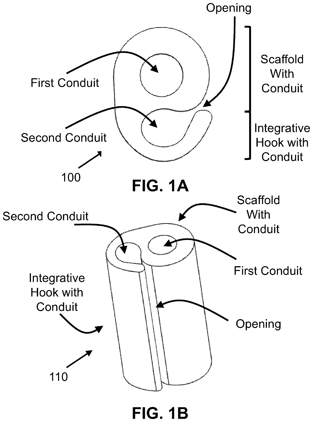
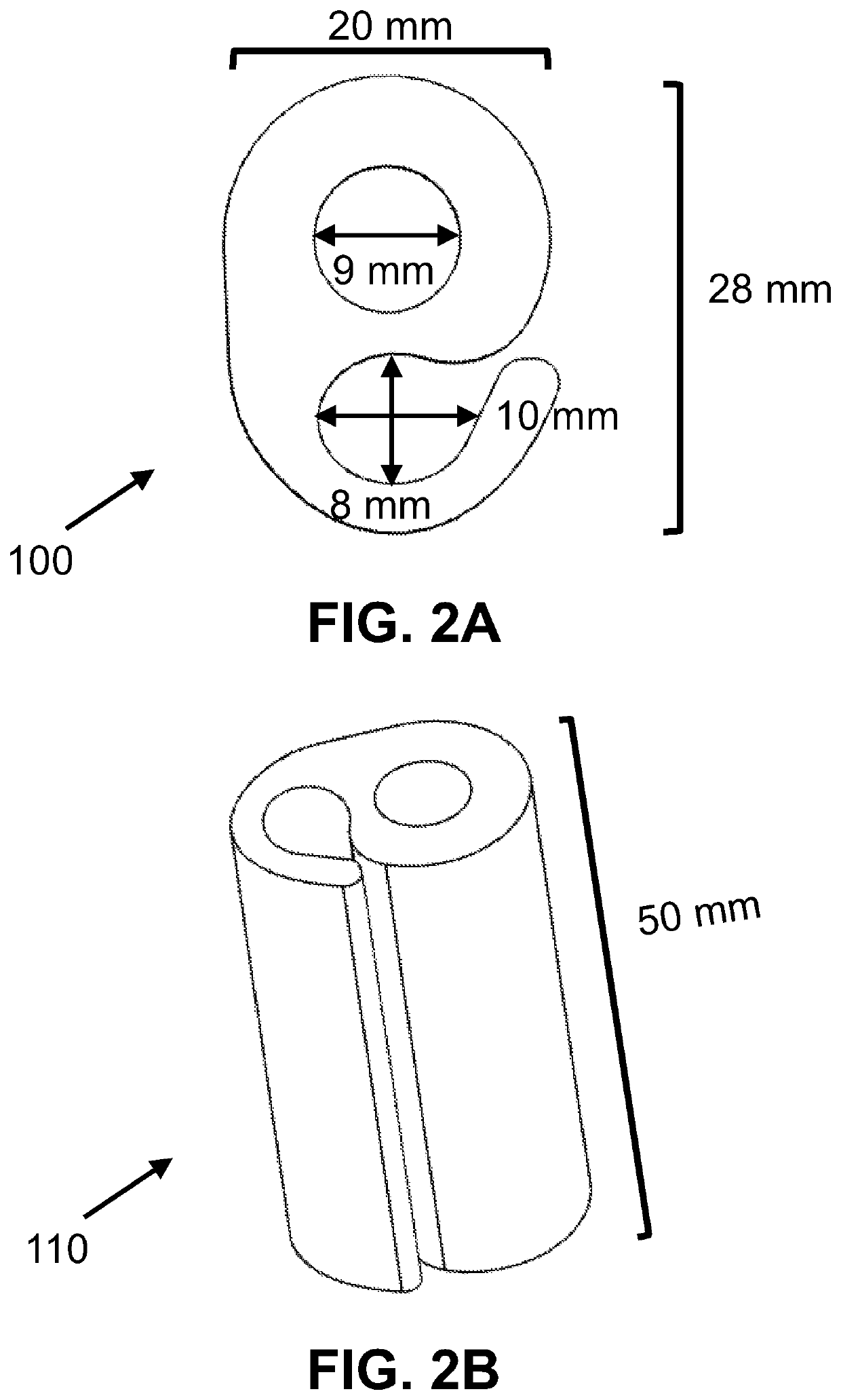
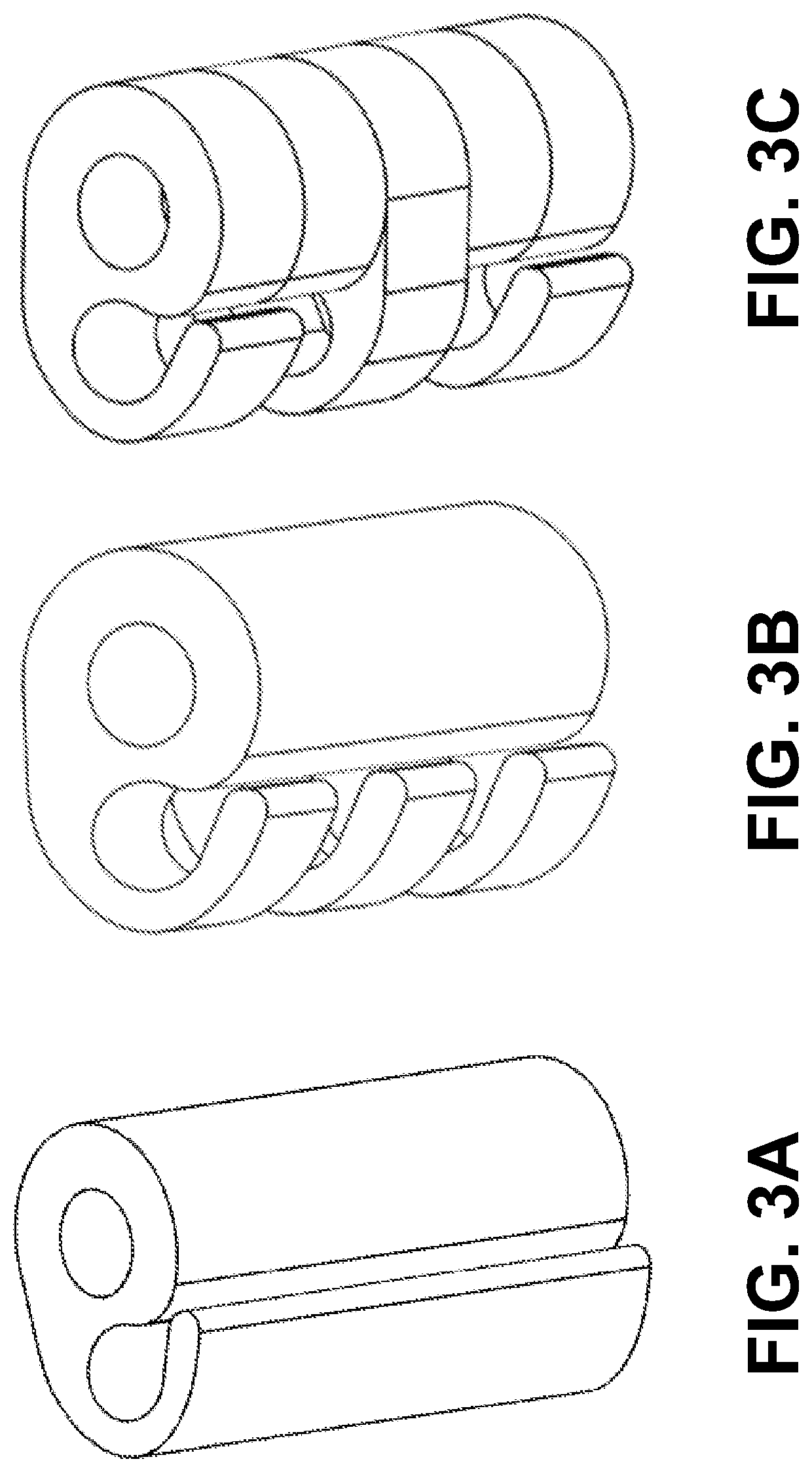
[0013]This invention pertains to a graft design for circumventing disadvantages of current clinical use of commercially available osteoinductive growth factors, and optimizing growth factor release for accelerated bone defect repair. The geometry of the device is distinguished by a scaffold section with a central conduit (first conduit), with either one or a series of hook-shaped chamber structures integrated and extending from a lateral side of the scaffold (FIGS. 1A-B, 2A-B and 3A-C). In one embodiment, the scaffold could be a tubular structure or a cylindrical structure. The purpose of the hook structures is to form a compartment or chamber, second conduit, to hold in place the biological augmentation device, such as growth factors (eg, recombinant human bone morphogenetic protein-2 (rhBMP-2) or platelet-derived growth factor BB (PDGF-BB) with carrier such as collagen sponge. In this case, the objective of the side hook is protection, so that during preparation and handling, the ...


PUM

PropertyMeasurementUnit
porosityaaaaaaaaaa
temperatureaaaaaaaaaa
thicknessaaaaaaaaaa

Abstract

A graft scaffold geometry is provided for use in the repair of segmental large bone defect. The scaffold geometry has a first (central) conduit with one or several hook-shaped chamber, which form a second conduit, integrated to the lateral side of the scaffold. The purpose of the hook-shaped chamber(s) is three-fold: 1) to facilitate the insertion and containment of biological augmentation constructs, such as growth factor-impregnated carrier devices; 2) stabilize the local surrounding soft tissue envelope to allow ingrowth of new blood vessels; and 3) to improve the manipulation of the composite bone free flap during implantation. Whether one or all of these mechanisms are active in a given situation, the overall result is that the hook chamber enables enhanced containment of graft-augmenting synthetic osteoinductive constructs, prevents their displacement, and maintains their proximity to the scaffold, thus improving the chances of success of the graft.

Description

FIELD OF THE INVENTION[0001]This invention relates to bone defect repair devices.BACKGROUND OF THE INVENTION[0002]Musculoskeletal diseases plague 30% of Americans and cost $950 billion per year, and each year more than a half million bone grafting surgeries are performed in the United States alone. Repair of large segmental bone defects still remains a significant clinical challenge. Despite much work to target this problem, vascularization remains a strategic barrier that prevents the translation of most bone tissue engineered constructs to clinical practice. The current technology will circumvent the harvesting of bone grafts, which causes skeletal morbidity in donor site and mismatch of anatomical shape. The present invention addresses solutions for large segmental long bone defects.SUMMARY OF THE INVENTION[0003]The present invention provides a personalized synthetic bioactive bone void filler or synthetic bioactive bone graft for large bone defect repair and regeneration. This b...

Claims


Application Information

Patent Timeline
Patent Type & Authority Patents(United States)
IPC IPC(8): A61F2/28A61F2/30
CPCA61F2/28A61F2/2846A61F2/3094A61F2002/2817A61F2002/2835A61F2002/30985A61F2002/3092
Inventor YANG, YUNZHIBRUYAS, ARNAUDGARDNER, MICHAEL J
Owner THE BOARD OF TRUSTEES OF THE LELAND STANFORD JUNIOR UNIV
Why Eureka
Try Eureka