Aircraft turbine rear structures

a technology of rear structure and turbine, which is applied in the direction of machines/engines, stators, mechanical equipment, etc., can solve the problems of limiting the amount of contoured vanes to turn the exhaust gas, too great an angle, and inhibiting the exhaust gas from leaving the engine at high speed, so as to improve the de-swirling effect

Active Publication Date: 2022-01-25
GKN AEROSPACE SWEDEN AB
View PDF11 Cites 0 Cited by
  • Summary
  • Abstract
  • Description
  • Claims
  • Application Information

AI Technical Summary

Benefits of technology

[0010]Each of the vanes in the first group of vanes is configured to cause exhaust gas passing over the respective vane to change direction, i.e., the vanes each have an aerodynamic profile or shape which is designed to cause exhaust gas entering the TRS to leave the TRS with a reduced component of swirl. This is achieved by providing each vane with a smooth aerodynamic shape.
[0011]The second group of splitter vanes substantially enhances the way in which the exhaust gas direction can be changed through the TRS. Put another way, the splitter vanes improve the de-swirling effect through the TRS.
[0018]The second group of vanes may extend across the whole distance between the central hub and the circumferential outer ring. Alternatively, the second group of vanes may extend a predetermined distance from the central hub. Thus, the second group of vanes may only be coupled at a first end to the central hub and have an opposing radially extending end terminating a predetermined radius from the central hub. Advantageously, this prevents any thermally induced loading on the vanes in the second group since the vane is permitted to expand within the TRS.
[0025]Overlapping a splitter vane over the point or region of maximum negative pressure (termed a “suction peak” herein) prevents or helps avoid separation of the exhaust gas flow from the vane. This further optimizes the gas turning effect.
[0028]The splitter vanes may advantageously be hollow in construction to minimise weight. This is particularly possible where the vanes are not load bearing vanes.

Problems solved by technology

However, there is a limit to how much the vanes can be contoured to turn the exhaust gas.
Too great an angle and the exhaust gas is inhibited from leaving the engine at high speed.
The matter is further complicated by separation of exhaust gas occurring at the surfaces of the turning vanes.

Method used


Image

  • Aircraft turbine rear structures
  • Aircraft turbine rear structures
  • Aircraft turbine rear structures

Examples


Embodiment Construction

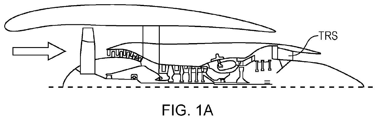
[0054]FIG. 1A shows the position of the turbine rear section (TRS) in a gas turbine engine.

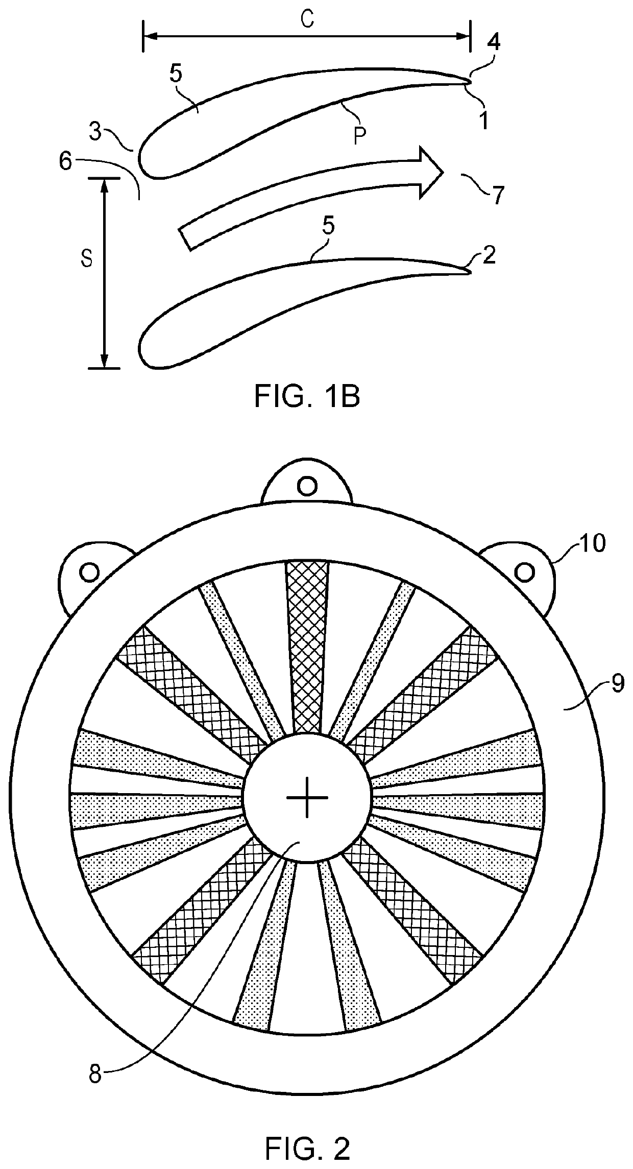
[0055]FIG. 1B shows a cross-section through a pair of adjacent guide vanes for a turbine rear structure (TRS). The TRS is located at the rear of the engine and provides a number of functions. For example, the TRS provides the structural connection for the engine to the aircraft body through lugs or mounts, which are described below.

[0056]The TRS functions aerodynamically to cause exhaust gas that has been generated by the turbine in the engine to leave the engine in a generally axial direction—that is parallel with the axis of rotation of the shaft running along the centre-line of the engine.

[0057]Returning to FIG. 1B, two adjacent vanes 1, 2 are shown. Each vane comprises a leading edge 3 and a trailing edge 4 and an aerodynamic profile 5, consisting of a suction side S (primarily convex) and a pressure side P (primarily concave) extending there between on each side of the vane.

[0058]A TRS co...


PUM

PropertyMeasurementUnit
radiusaaaaaaaaaa
radiusaaaaaaaaaa
distanceaaaaaaaaaa

Abstract

A turbine rear structure for a gas turbine engine includes a central hub and a circumferential outer ring coaxial with the central hub. The turbine rear structure further includes a plurality of guide vanes extending radially between the central hub and the circumferential outer ring, and an intermediate guide vane located in a space defined between adjacent guide vanes. The intermediate guide vane is located closer to one of the guide vanes than the other guide vane.

Description

CROSS-REFERENCE TO RELATED APPLICATIONS[0001]This application is a national stage of, and claims priority to, Patent Cooperation Treaty Application No. PCT / EP2018 / 080306, filed on Nov. 6, 2018, which application claims priority to Great Britain Application No. GB 1718405.2, filed on Nov. 7, 2017, which applications are hereby incorporated herein by reference in their entireties.BACKGROUND[0002]In a gas turbine engine of the type used in commercial aircraft, a gas turbine generates the thrust for the aircraft. Air is received at the front of the engine, compressed, and mixed with fuel before being ignited and generating a flow of high-speed exhaust gases. Because of the continuous rotation of the blades within the engine, the gases similarly swirl or circulate around the axis of the engine. It is advantageous to compensate for this swirl so as to direct gases out of the rear of the engine in a direction opposite to that of flight.[0003]This maximizes the thrust that is generated sinc...

Claims


Application Information

Patent Timeline
Patent Type & Authority Patents(United States)
IPC IPC(8): F01D17/14F01D9/04F01D5/14F01D25/30
CPCF01D17/141F01D9/041F05D2220/323F05D2230/30F05D2230/60F01D5/143F01D25/30F05D2230/31F05D2230/54F01D5/146Y02T50/60F01D5/145F05D2240/126Y10T29/49323
Inventor WALLIN, FREDRIK
Owner GKN AEROSPACE SWEDEN AB
Why Eureka
Try Eureka