Supercharge Your Innovation With Domain-Expert AI Agents!

Internal combustion engine

a combustion engine and combustion chamber technology, applied in the direction of combustion engine, machine/engine, liquid fuel feeder, etc., can solve the problems of only possible or inability to dispose of water in the atmosphere, pollution in the atmosphere, and inability to achieve environmental friendly disposal, etc., to achieve easy maintenance, reduce production costs of water injectors, and reduce the effect of materials

Active Publication Date: 2022-01-25
DR ING H C F PORSCHE AG
View PDF17 Cites 0 Cited by
  • Summary
  • Abstract
  • Description
  • Claims
  • Application Information

AI Technical Summary

Benefits of technology

[0007]In view of the foregoing challenges, described herein is an internal combustion engine which, in a simple and economic fashion, allows the re-use of the water flowing out of the crankcase and the environmentally friendly disposal of the water.
[0009]Because of the high temperature prevailing in the crankcase, the water in the crankcase is in vapor form. When the blow-by mixture containing the injection water flows through the crankcase ventilation device and hence through the activated charcoal filter, the blow-by mixture cools such that the water liquefies and thereby separates from the remaining gaseous constituents of the blow-by mixture. By flowing through the activated charcoal filter, the blow-by mixture and in particular the water downstream of the activated charcoal filter is freed from hydrocarbons, so that the water is harmless to the environment and can be discharged to the environment.
[0012]Preferably, the water injection device has a water injector which is arranged in an intake tract that can be fluidically connected to the cylinder, wherein the intake air carries the injected water into the cylinder. In this way, the water injection is simplified and the production costs of the water injector are reduced, since the thermal load on the water injector is lower and thereby cheaper materials may be used for producing the water injector.
[0014]Thus an internal combustion engine is created with a water injection, wherein the water flowing with the blow-by mixture into the crankcase and into the crankcase ventilation device is cleaned of hydrocarbons in a simple and economic fashion, and can thereby be discharged to the atmosphere in an environmentally friendly manner or reused in the water injection system.

Problems solved by technology

It is a problem that water flowing into the collection tank or discharged into the atmosphere contains pollutants, in particular hydrocarbons, wherein both reuse of the polluted water for injection into the intake tract and environmentally friendly disposal of the water to atmosphere are not possible or only possible with limitations.

Method used


Image

  • Internal combustion engine
  • Internal combustion engine

Examples


Embodiment Construction

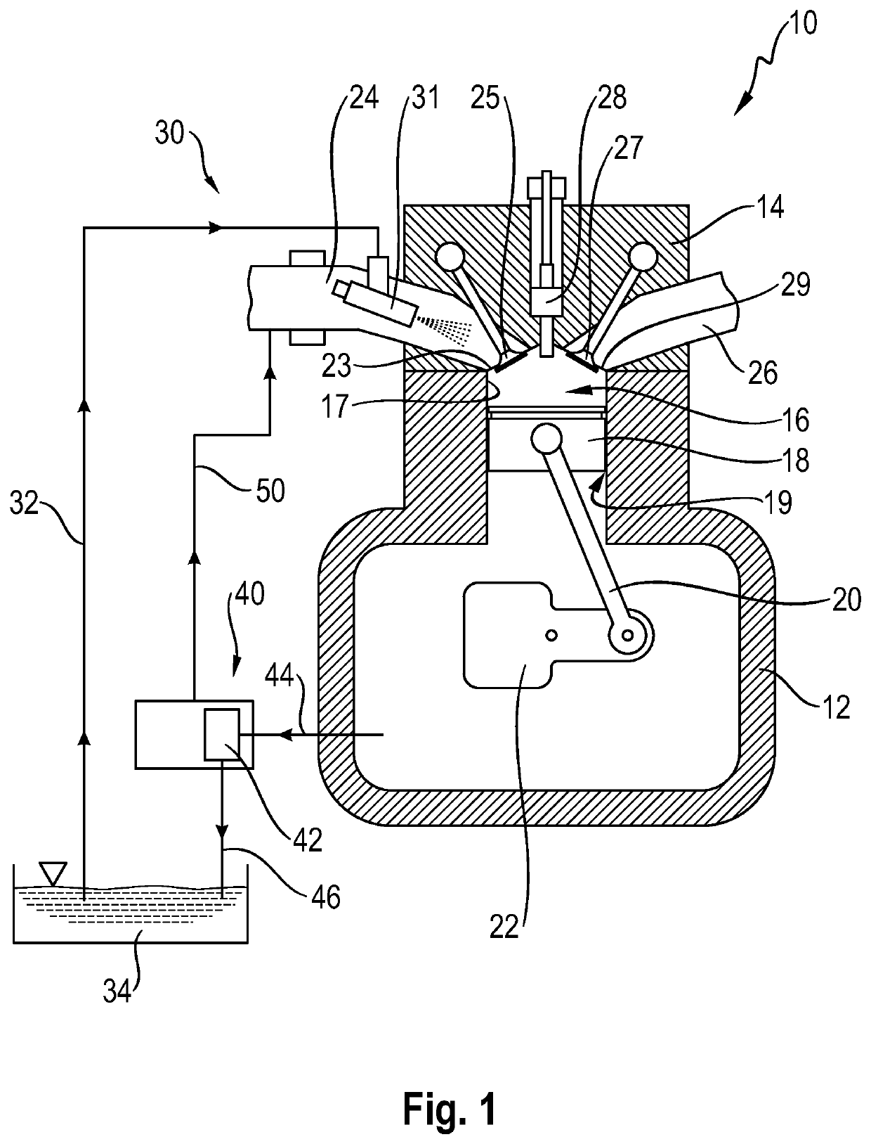
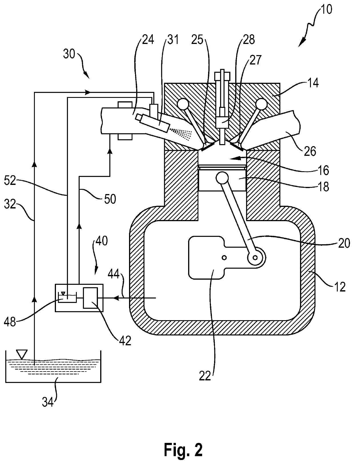
[0018]FIG. 1 discloses an internal combustion engine 10 of a motor vehicle. The internal combustion engine 10 has a crankcase 12, a cylinder head 14 and several cylinders 16, wherein the figures show only one cylinder 16. A piston 18, which moves in oscillation during operation of the internal combustion engine 10, is arranged in the cylinder 16. The piston 18 is connected to a connecting rod 20, wherein a first end of the connecting rod is rotatably attached to the piston 18 and a second end is rotatably and eccentrically connected to a crankshaft 22. During operation of the internal combustion engine 10, the piston 18 moves in oscillation between a bottom dead center and a top dead center.

[0019]Above the top dead center, the cylinder 16 has an inlet 23 which is fluidically connected to an air intake tract 24. The inlet 23 can be closed by an inlet valve 25, wherein the inlet valve 25 opens and closes the inlet 23 as required. Also above the top dead center and adjacent to the inle...


PUM


Abstract

An internal combustion engine includes a crankcase and a cylinder head. The cylinder head and the crankcase delimit at least one cylinder in which a translationally moving piston is arranged. A water injection device injects water into the at least one cylinder. A crankcase ventilation device is fluidically connected to the crankcase. A blow-by mixture containing injection water can flow through the crankcase ventilation device. The crankcase ventilation device has an activated charcoal filter. The blow-by mixture containing the injection water can flow through the activated charcoal filter.

Description

CROSS REFERENCE TO RELATED APPLICATION[0001]This application claims priority to German Patent Application No. 10 2020 108 134.0, filed Mar. 25, 2020, the content of such application being incorporated by reference herein in its entirety.FIELD OF THE INVENTION[0002]The invention concerns an internal combustion engine with a crankcase, a cylinder head, wherein the cylinder head and the crankcase delimit at least one cylinder in which a translationally moving piston is arranged, a water injection device for injecting water into the at least one cylinder, and a crankcase ventilation device which is fluidically connected to the crankcase, wherein a blow-by mixture containing injection water can flow through the crankcase ventilation device.BACKGROUND OF THE INVENTION[0003]Such internal combustion engines have been known for a long time. During operation of the internal combustion engines, a gas-oil mixture from a cylinder of the internal combustion engine passes through a movement gap, f...

Claims


Application Information

Patent Timeline
Patent Type & Authority Patents(United States)
IPC IPC(8): F02M37/24F02B47/02
CPCF02B47/02F02M37/24F02M25/06F02M25/028F02M25/0221F02M25/0224F01M13/04F02M35/10222F01M2013/0477Y02T10/12
Inventor FABER, HENRIK
Owner DR ING H C F PORSCHE AG
Features
  • R&D
  • Intellectual Property
  • Life Sciences
  • Materials
  • Tech Scout
  • Unparalleled Data Quality
  • Higher Quality Content
  • 60% Fewer Hallucinations
Learn More