
Power sources and transmission networks for auxiliary equipment onboard hydraulic fracturing units and associated methods

a technology of hydraulic fracturing unit and transmission network, which is applied in the direction of piston pumps, positive displacement liquid engines, borehole/well accessories, etc., can solve the problems of fracturing fluid displacement, fracturing failure and fracture, pump crank turning and displacing fracturing fluid

Active Publication Date: 2022-02-01
BJ ENERGY SOLUTIONS LLC
View PDF1160 Cites 80 Cited by
  • Summary
  • Abstract
  • Description
  • Claims
  • Application Information

AI Technical Summary

Problems solved by technology

As a result, pressure builds rapidly to the point where the formation fails and begins to fracture.
When a gear is selected at the transmission the diesel engine may then transfer power and torque through to the pump resulting in the pumps crank turning and displacing fracturing fluid.
The use of electric power to drive fracturing pumps does not eliminate the requirement for onboard auxiliary equipment, but the utilization of high-voltage power may be conditioned and transformed into low voltages to run pumps, cooling equipment and other auxiliary equipment.
Although it may appear that an electric fracturing well site is also less congested than a diesel engine fracturing well site, both are often comparably congested.
Despite the vehicle and machinery count on location, the power utilization to both the pump and auxiliary equipment does often prove to be more efficient with electric motor efficiencies being greater than that of its hydraulic counterpart; however, the capital cost to implement such electric equipment and circuitry is far greater.
The gas turbine engine has dual shafts with the output shaft reaching speeds of up to 16,000 revolutions per minute (RPM), and this makes running a PTO directly from the engine's output shaft a complex and costly development.

Method used


Image

  • Power sources and transmission networks for auxiliary equipment onboard hydraulic fracturing units and associated methods
  • Power sources and transmission networks for auxiliary equipment onboard hydraulic fracturing units and associated methods
  • Power sources and transmission networks for auxiliary equipment onboard hydraulic fracturing units and associated methods

Examples


Embodiment Construction

[0039]Some implementations of the present disclosure will now be described more fully hereinafter with reference to the accompanying figures, in which some, but not all implementations of the disclosure are shown. Indeed, various implementations of the disclosure may be embodied in many different forms and should not be construed as limited to the implementations set forth herein; rather, these example implementations are provided so that this disclosure will be thorough and complete, and will fully convey the scope of the disclosure to those skilled in the art. Like reference numerals refer to like elements throughout.

[0040]Unless specified otherwise or clear from context, references to first, second or the like should not be construed to imply a particular order. A feature may be described as being above another feature (unless specified otherwise or clear from context) may instead be below, and vice versa; and similarly, features described as being to the left of another feature ...


PUM


Abstract

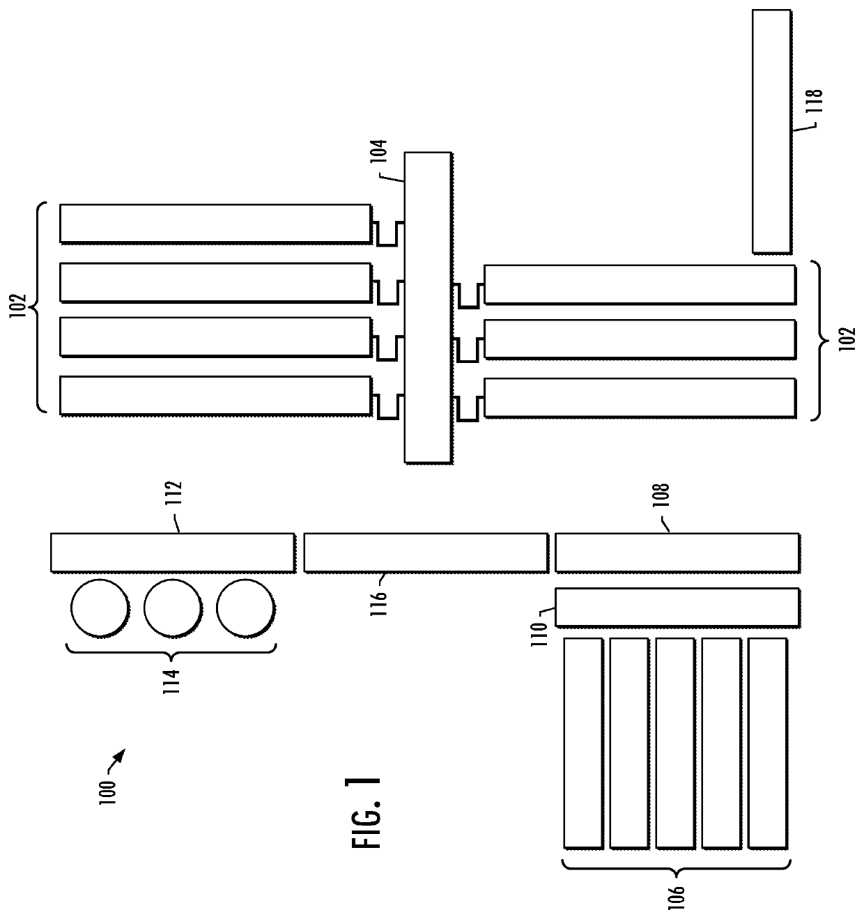
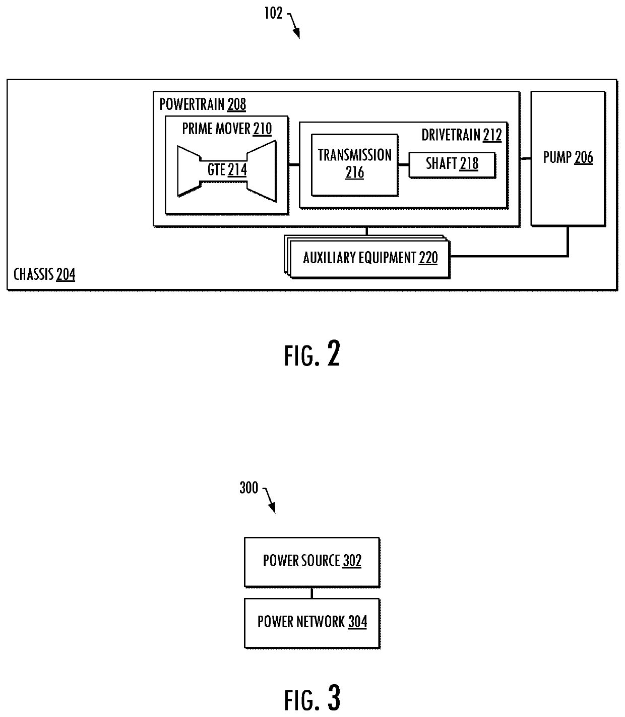
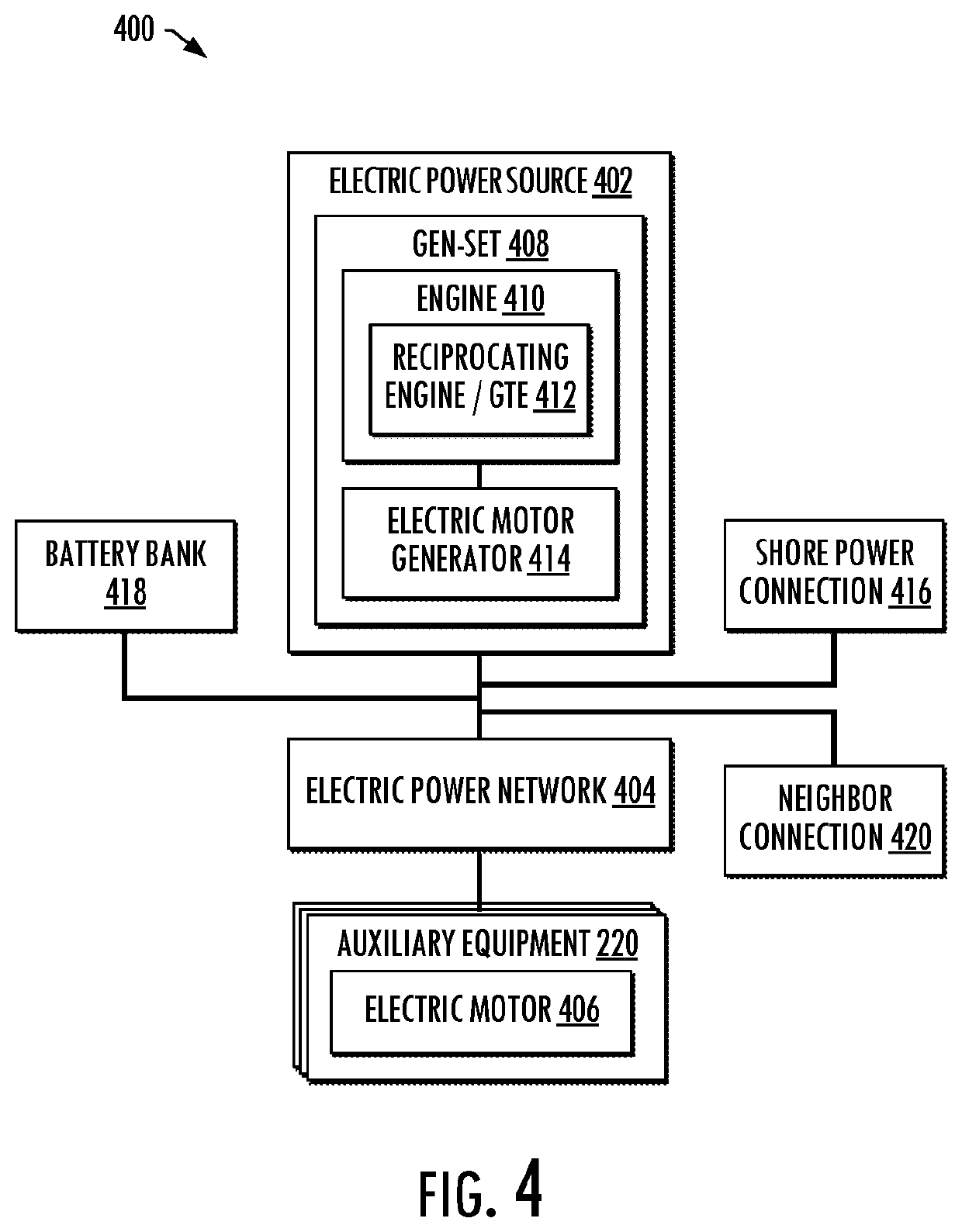
Embodiments of systems and methods disclosed provide a hydraulic fracturing unit that includes a reciprocating plunger pump configured to pump a fracturing fluid and a powertrain configured to power the reciprocating plunger pump. The powertrain includes a prime mover and a drivetrain, the prime mover including a gas turbine engine. The hydraulic fracturing unit also includes auxiliary equipment configured to support operation of the hydraulic fracturing unit including the reciprocating plunger pump and the powertrain. A power system is configured to power the auxiliary equipment. The power system includes a power source and a power network. The power source is configured to generate power for the auxiliary equipment. The power network is coupled to the power source and the auxiliary equipment, and configured to deliver the power generated by the power source to the auxiliary equipment. Associated systems including a plurality of hydraulic fracturing units are also provided.

Description

CROSS-REFERENCE TO RELATED APPLICATION(S)[0001]This application is a divisional of U.S. Non-Provisional application Ser. No. 16 / 946,079, filed Jun. 5, 2020, titled “POWER SOURCES AND TRANSMISSION NETWORKS FOR AUXILIARY EQUIPMENT ONBOARD HYDRAULIC FRACTURING UNITS AND ASSOCIATED METHODS,” which claims the benefit of and priority to U.S. Provisional Patent Application No. 62 / 899,971, filed Sep. 13, 2019, titled “AUXILIARY DRIVE SYSTEMS AND ALTERNATIVE POWER SOURCES,” the entire disclosures of each of which are incorporated herein by reference.TECHNOLOGICAL FIELD[0002]This disclosure relates generally to fracturing operations for oil and gas wells, and in particular, to power sources and networks for auxiliary equipment onboard hydraulic fracturing units and associated methods.BACKGROUND[0003]Fracturing is an oilfield operation that stimulates production of hydrocarbons, such that the hydrocarbons may more easily or readily flow from a subsurface formation to a well. For example, a fra...

Claims


Application Information

Patent Timeline
Patent Type & Authority Patents(United States)
IPC IPC(8): F04B17/05H02J9/00F04B23/04E21B43/26H02K7/18F04B15/02F04B53/08F04B9/02F04B17/03F04B53/18F01M1/02F01P3/20F01M1/12
CPCF04B17/05F04B9/02F04B15/02F04B17/03F04B23/04F04B53/08F04B53/18H02J9/00H02K7/1823E21B43/2607F01M1/02F01M1/12F01M2001/0253F01P3/20F04B9/10F04B47/02F04B23/06F16N2210/02F16N19/006F16N2200/00F16N2200/02F16N2270/10F16N2270/50H02J9/062H02J9/066H02J9/06
Inventor YEUNG, TONYRODRIGUEZ-RAMON, RICARDOFOSTER, JOSEPHTEW, NICHOLAS
Owner BJ ENERGY SOLUTIONS LLC
Learn More