Multipart balanced piston clutch

a multi-balanced, clutch technology, applied in the direction of clutches, mechanical equipment, transportation and packaging, etc., can solve the problems of reducing the capacity and efficiency of the clutch, the clutch may not be able to engage or be prevented from disengaging, and the maximum speed of the vehicle may be limited, so as to increase the collective surface area, increase the surface area, and increase the effect of radial distan

Active Publication Date: 2022-02-01
INC BLUE LEAF I
View PDF19 Cites 0 Cited by
  • Summary
  • Abstract
  • Description
  • Claims
  • Application Information

AI Technical Summary

Benefits of technology

[0007]In one exemplary embodiment formed in accordance with the present invention, there is provided a clutch assembly for a transmission of an agricultural work vehicle. The clutch assembly includes a housing, a clutch pack located within the housing, a piston chamber located within the housing, a multipart piston located within and slidable relative to the piston chamber, and a balance chamber. The multipart piston includes a lower piston extension part. The lower boundary wall of the balance chamber and the lower boundary wall of the piston chamber are radially separated from one another by a substantial distance. This distance allows the balance chamber to provide a greater balance force to counteract a centrifugal head force acting on the piston. The lower piston extension part is located within the balance chamber for adding to a collective surface area of the balance chamber. The lower piston extension part may be vented for preventing a build up of fluid in an area behind the lower piston extension part.
[0010]One possible advantage of the exemplary embodiment of the agricultural vehicle is that the balance chamber provides for a substantial balance force for counteracting a centrifugal head force acting on the piston as a result of an increased radial distance between the lower boundary walls of the piston chamber and the balance chamber.
[0011]Another possible advantage of the exemplary embodiment of the agricultural vehicle is that the piston includes a lower piston extension part which increases the collective surface area of the balance chamber.
[0012]Yet another possible advantage of the exemplary embodiment of the agricultural vehicle is that the increased surface area in the balance chamber can create a balance force greater than the centrifugal head force if the radial separation between the piston inner diameter and the balance chamber inner diameter is large enough, which is made possible by the multipart piston.

Problems solved by technology

Typically, the springs resist the centrifugal head force; however, if the centrifugal head force becomes greater than the return force of the springs then the clutch may undesirably engage or be prevented from disengaging.
Thus, the maximum speed of the vehicle may be limited as a result of the centrifugal head force interfering with the operation of the piston clutch.
The stronger springs can withstand a greater centrifugal force; however, such springs directly reduce the capacity and efficiency of the clutch.

Method used


Image

  • Multipart balanced piston clutch
  • Multipart balanced piston clutch
  • Multipart balanced piston clutch

Examples


Embodiment Construction

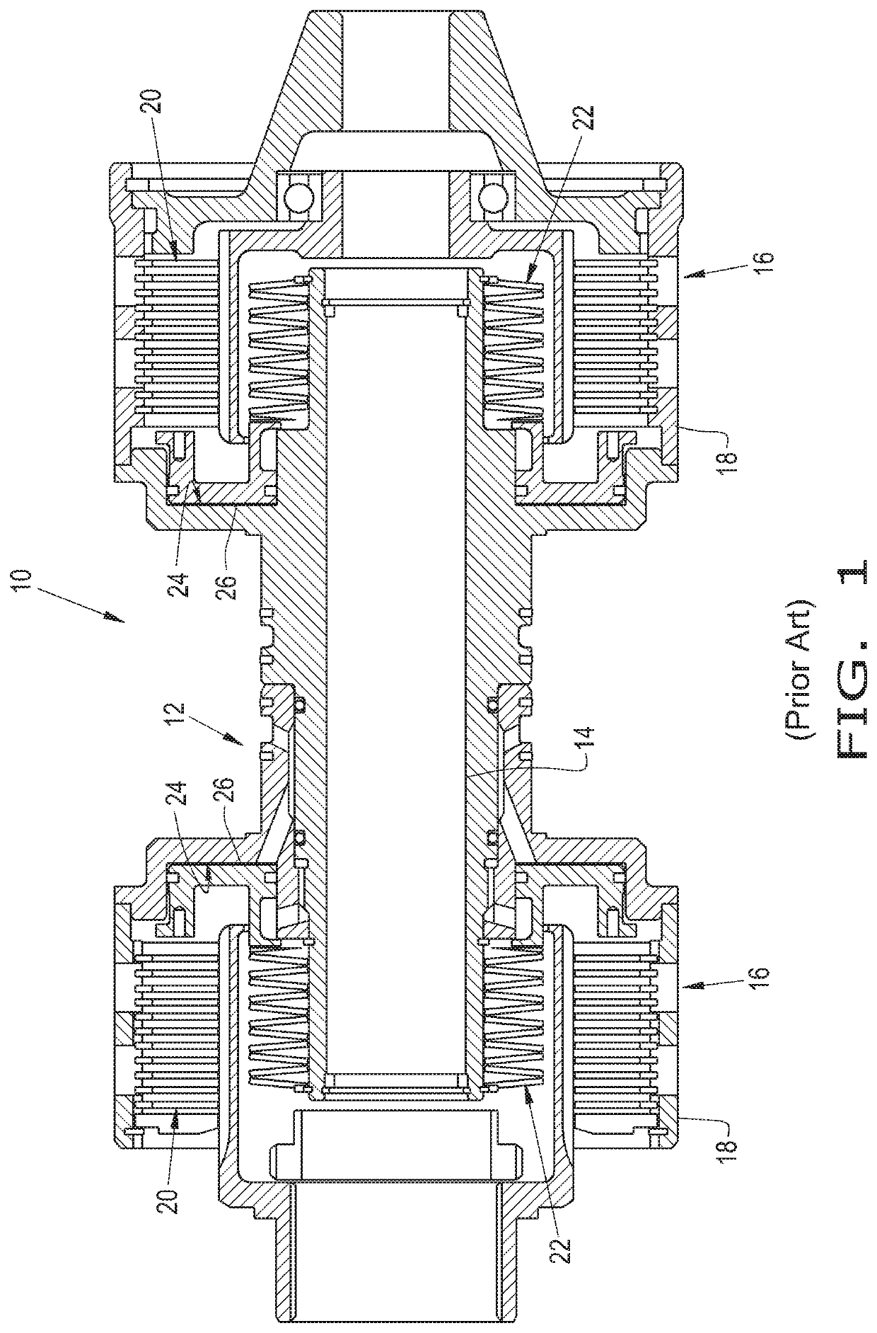
[0017]Referring now to the drawings, and more particularly to FIG. 1, there is shown an agricultural work vehicle 10 which generally includes a chassis, wheels and / or tracks supporting the chassis, an engine for providing motive power, a transmission 12, and a driveline for transferring the motive power to the wheels. The agricultural work vehicle 10 may be in the form of any desired work vehicle such as a tractor or windrower.

[0018]The transmission 12 is supported by the chassis and generally includes a shaft 14, two annular clutch assemblies 16, and a hydraulic system for operating the clutch assemblies 16 in order to cycle through the gears of the agricultural work vehicle 10. The transmission 12 is a continuously variable transmission (CVT). Each clutch assembly 16 may generally include a housing 18, a clutch pack 20, multiple Belleville spring washers 22, a piston chamber 24, and a piston 26 disposed within the piston chamber 24.

[0019]As each clutch assembly 16 spins along with...


PUM


Abstract

A clutch assembly for a transmission of an agricultural work vehicle. The clutch assembly includes a housing, a clutch pack located within the housing, a piston chamber located within the housing, and a multipart piston located within and slidable relative to the piston chamber. The multipart piston is operably connected to the clutch pack for engaging and disengaging the clutch pack. The multipart piston includes a lower piston extension part. The clutch assembly further includes a balance chamber that is located within the housing. The lower boundary wall of the balance chamber and the lower boundary wall of the piston chamber are radially separated from one another by a substantial distance. The lower piston extension part is located within the balance chamber for adding to a collective surface area of the balance chamber.

Description

BACKGROUND OF THE INVENTION[0001]The present invention pertains to a driveline of a vehicle and, more specifically, to a hydraulically operated clutch assembly for the driveline of a work vehicle.[0002]A work vehicle, such as a large truck or tractor, generally includes a chassis, wheels and / or tracks supporting the chassis, an engine, such as a diesel engine, a transmission, and a drivetrain. The transmission may transmit the motive force, in various gear ratios, to the wheels through the drivetrain which may selectively couple the drive axles in order to operate the vehicle in one or more tractive, i.e., drive, configurations. Work vehicles typically run at or near the operational capacity of their engines due to the power demands required for earth moving and / or towing various implements. Hence, it is generally critical to rapidly shift between gears to maintain sufficient power at the wheels.[0003]The transmission may include one or more clutch assemblies operably connected in b...

Claims


Application Information

Patent Timeline
Patent Type & Authority Patents(United States)
IPC IPC(8): F16D25/12F16D48/02F16J1/00F16J1/09F16D25/0638B60K17/02
CPCF16D25/14B60K17/02F16D25/0638F16J1/005F16J1/09F16D25/12
Inventor JENSEN, MICHAEL R.PAYNE, DANIEL
Owner INC BLUE LEAF I
Why Eureka
Try Eureka