

Mask structure for deposition device, deposition device, and operation method thereof
- Summary
- Abstract
- Description
- Claims
- Application Information
AI Technical Summary
Benefits of technology
Problems solved by technology
Method used
Image

Examples
first embodiment
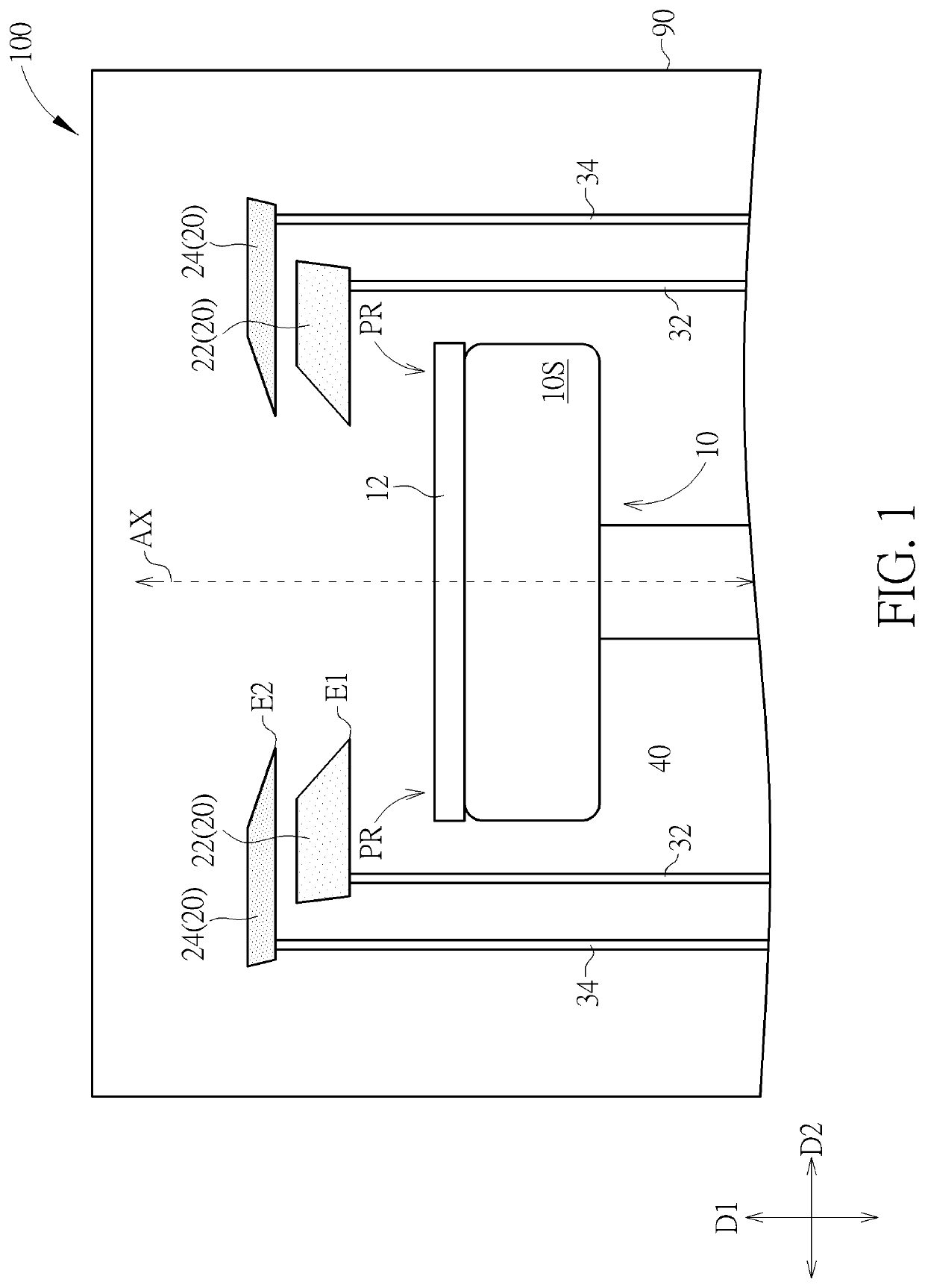
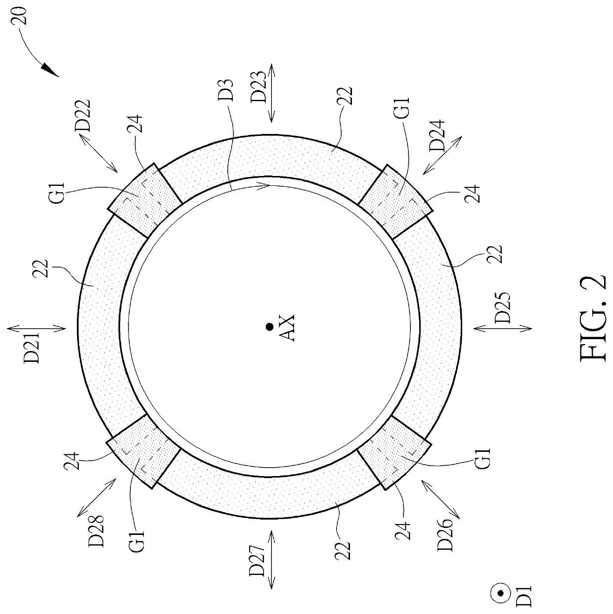
[0027]FIG. 1 is a schematic drawing illustrating a deposition device according to the present invention, and FIG. 2 is a schematic drawing illustrating a top view of a mask structure for a deposition device in this embodiment. As illustrated in FIG. 1 and FIG. 2, a mask structure 20 for a deposition device is provided. The mask structure 20 includes a plurality of first segments 22 and a plurality of second segments 24. The first segments 22 are arranged in a direction surrounding a central axis AX (such as a direction D3 represented in FIG. 2) and separated from one another. The second segments 24 are disposed above the first segments 22. Each of the second segments 24 overlaps two of the first segments 22 adjacent to each other in a vertical direction D1 parallel to an extending direction of the central axis AX. The mask structure 20 may be used in a deposition device, such as a deposition device 100 represented in FIG. 1, but not limited thereto. In other words, the mask structur...
second embodiment
[0045]FIG. 11 is a schematic drawing illustrating a top view of a mask structure for a deposition device according to the present invention. As illustrated in FIG. 11, in the deposition device of this embodiment, more than one of the first supporting structures 32 may be connected to one of the first segments 22, and more than one of the second supporting structures 34 may be connected to one of the second segments 24 for improving the supporting performance for the first segments 22 and the second segments 24. In some embodiments, the second supporting structures 34 may be disposed under the outer portion of the corresponding second segment 24 for avoiding interfering with the movements of the first segments 22, but not limited thereto.
third embodiment
[0046]FIG. 12 is a schematic drawing illustrating a loading operation in an operation method of the deposition device according to the present invention, FIG. 13 is a top view schematic drawing illustrating the loading operation in the operation method of the deposition device in this embodiment, and FIG. 14 is a schematic drawing illustrating a portion of the mask structure 20 for the deposition device in this embodiment. As illustrated in FIG. 12 and FIG. 13, in the loading operation of this embodiment, the lifting structures 40 may penetrate through the holding structure 10S for lifting the substrate 12 up to a position away from the holding structure 10S, and the loading structure 50 may extend to the space between the substrate 12 and the holding structure 10S for transferring the substrate 12 out of the process chamber 90 after a deposition process performed to the substrate 12. Similarly, a substrate 12 may be transferred into the process chamber 90 and be placed on the lifti...
PUM
| Property | Measurement | Unit |
|---|---|---|
| Angle | aaaaa | aaaaa |
| Length | aaaaa | aaaaa |
Abstract
Description
Claims
Application Information