Valve gear and engine

a valve gear and valve gear technology, applied in the direction of valve arrangement, machine/engine, auxiliary lubrication, etc., can solve problems such as increasing problems, and achieve the effects of stable hydraulic pressure, reduced cross-sectional area, and reduced delay respons

Active Publication Date: 2022-02-22
YAMAHA MOTOR CO LTD
View PDF24 Cites 0 Cited by
  • Summary
  • Abstract
  • Description
  • Claims
  • Application Information

AI Technical Summary

Benefits of technology

[0008]According to a preferred embodiment of the present invention, the first support includes on its outer surface the first concave portion connected to the first oil path such that it becomes possible to reduce a decrease in a cross-sectional area in the first oil path where the junction is made with the first support, and the second concave portion connected to the second oil path such that it becomes possible to reduce a decrease in a cross-sectional area in the second oil path where the junction is made with the first support. Also, the second support includes on its outer surface the third concave portion connected to the first oil path such that it becomes possible to reduce a decrease in a cross-sectional area in the first oil path where the junction is made with the second support, and the fourth concave portion connected to the second oil path such that it becomes possible to reduce a decrease in a cross-sectional area in the second oil path where the junction is made with the second support. Therefore, it is possible to reduce a delayed response in the connection-switching hydraulic pressure in the rocker arm, and in the lubrication hydraulic pressure between the rocker arm and the cam, and to supply a stable hydraulic pressure.
[0019]Further preferably, the cylinder head includes a plurality of cylinders located axially along the rocker shaft, the first insertion hole and the second insertion hole are provided for each cylinder and located axially along the rocker shaft, the valve gear is provided for each cylinder, and each of the first oil path and the second oil path extends axially along the rocker shaft and is shared by the plurality of valve gears. In this case, it is possible to reduce the amount of decrease in the cross-sectional area in the first oil path where the junction is made with the first support and the second support in each valve gear, and to reduce the amount of decrease in the cross-sectional area in the second oil path where the junction is made with the first support and the second support in each valve gear. Therefore, it is possible to reduce a gap in the response in the connection-switching hydraulic pressure of the rocker arm between the valve gears, and to supply a sufficient amount of lubrication oil even between the rocker arm and the cam are located far from the hydraulic pressure source. Therefore, preferred embodiments of the present invention are suitable for a multi-cylinder engine which includes a plurality of cylinders disposed in-line.

Problems solved by technology

The problem becomes more significant with an increasing amount of overlap between the first oil path and the first support or the second support, and with an increasing amount of overlap between the second oil path and the first support or the second support.

Method used


Image

  • Valve gear and engine
  • Valve gear and engine
  • Valve gear and engine

Examples


Embodiment Construction

[0037]Hereinafter, preferred embodiments of the present invention will be described with reference to the drawings.

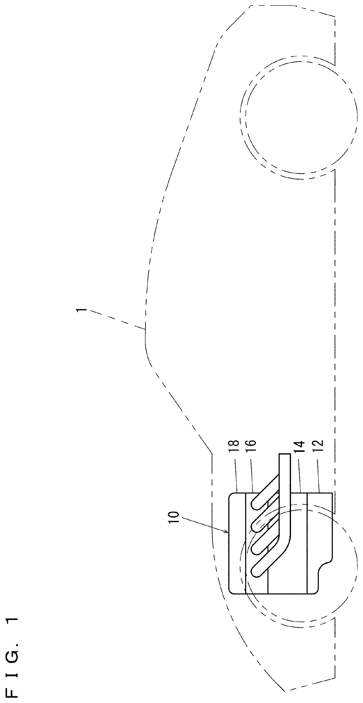
[0038]Referring to FIG. 1, an engine 10 according to a preferred embodiment of the present invention is installed in an automobile 1 and is used as a propelling source of the automobile 1.

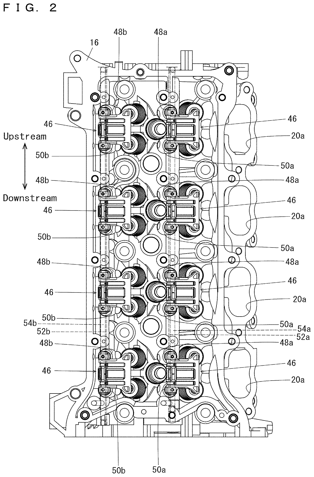
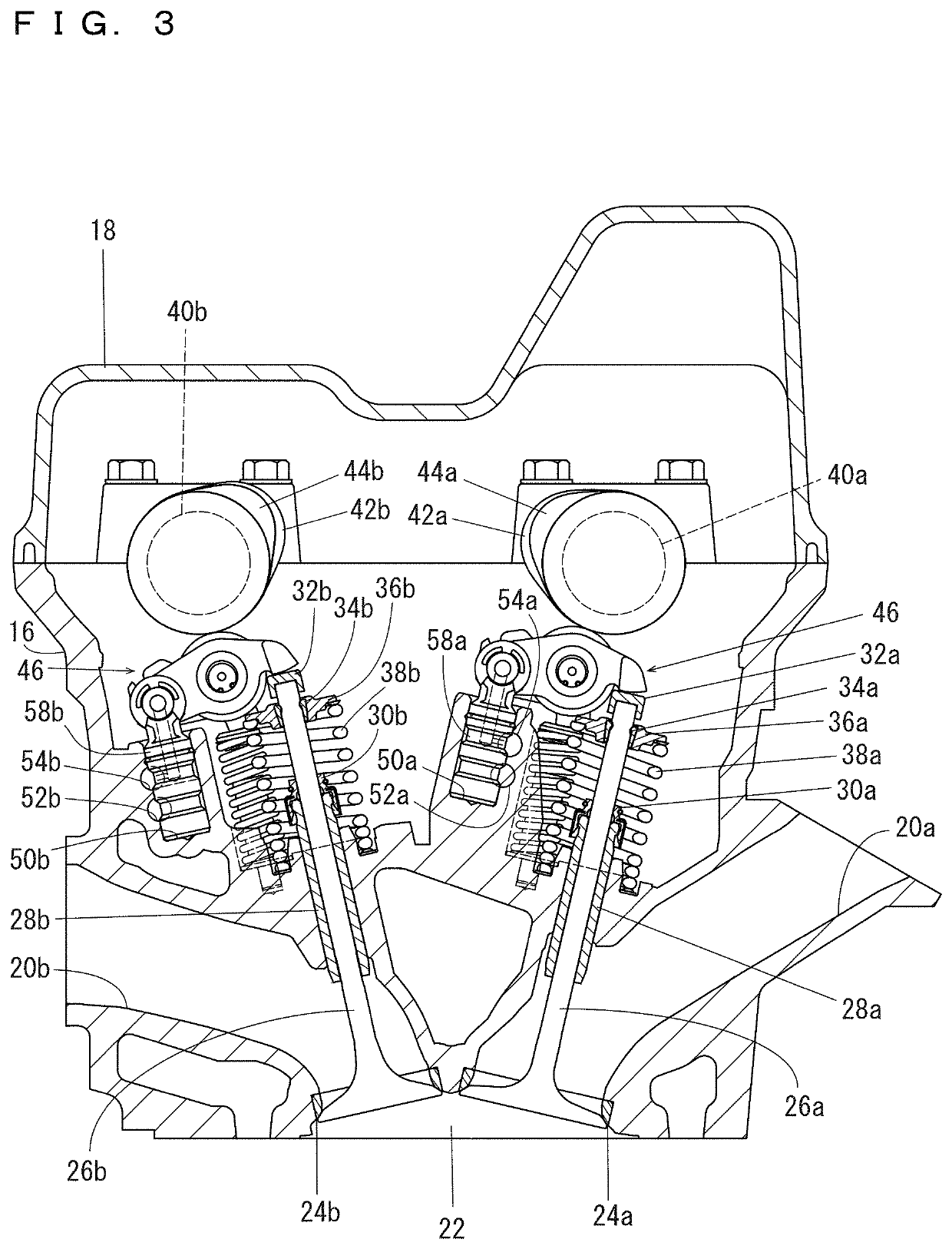
[0039]Referring also to FIG. 2 and FIG. 3, the engine 10 is a multi-cylinder engine which includes a plurality of cylinders, and in the present preferred embodiment, is a straight four-cylinder engine. The engine 10 includes a crank case 12 which houses a crank shaft (not illustrated), a cylinder block 14 connected with the crank case 12, a cylinder head 16 connected with the cylinder block 14, and a cylinder head cover 18 attached to the cylinder head 16.

[0040]The cylinder block 14 includes a plurality of cylinders located axially along a rocker shaft 56 (which will be described below). For each cylinder, a combustion chamber 22 is provided in the cylinder block 14 and the cylinder he...


PUM


Abstract

An engine includes a cylinder head including a first oil path and a second oil path. The cylinder head includes a valve gear including a first support and a second support that support a rocker shaft. The first support includes, on its outer surface, a first constriction located at an inlet of a connection-switching third oil path and connected to the first oil path, and a second constriction connected to the second oil path. The second support includes, on its outer surface, a third constriction connected to the first oil path, and a fourth constriction located at an inlet of a lubrication fourth oil path and connected to the second oil path.

Description

CROSS REFERENCE TO RELATED APPLICATIONS[0001]This application claims the benefit of priority to Japanese Patent Application No. 2019-239843 filed on Dec. 27, 2019. The entire contents of this application are hereby incorporated herein by reference.BACKGROUND OF THE INVENTION1. Field of the Invention[0002]The present invention relates to valve gears and engines, and more specifically to a valve gear and an engine able to change a lift amount, an opening timing, and a closing timing of a valve.2. Description of the Related Art[0003]JP-A 2009-91971 discloses an example pertinent to conventional techniques of this kind. JP-A 2009-91971 discloses a variable valve mechanism which includes a rocker arm provided with a switching mechanism for hydraulically changing a valve opening amount, and two rocker arm support members provided at a widthwise distance of the rocker arm for supporting the rocker arm. In the variable valve mechanism, each rocker arm support member has a fitting portion fo...

Claims


Application Information

Patent Timeline
Patent Type & Authority Patents(United States)
IPC IPC(8): F01M9/10F01L1/053F01L1/18
CPCF01M9/105F01L1/053F01L1/18F01L1/181F01L2001/0537F01L2001/186F01L2810/02F01L1/26
Inventor OKAMOTO, YASUO
Owner YAMAHA MOTOR CO LTD
Why Eureka
Try Eureka