Near-eye foveal display

a display system and near-eye technology, applied in the field of display systems, can solve problems such as cumbersomeness and burden, and achieve the effects of high quality, great depth of field, and efficient display of the highest quality portion of an imag

Active Publication Date: 2022-02-22
SOLIDDD
View PDF3 Cites 3 Cited by
  • Summary
  • Abstract
  • Description
  • Claims
  • Application Information

AI Technical Summary

Benefits of technology

[0013]The lens array is of the general category of an integral imaging, plenoptic system, as is commonly known to those well versed in the art. As such, each lens in the array provides a complete image which might be viewed alone as a comprehensible image; each such image presented by the lens array is a portion of the overall image seen by the viewer, herewith to be called the reference image. Each lens in the foveal display provides a high quality portion of the reference image through an individual lens. The given portion of the reference image presented by each lens is a product of a calculation dependent on the location of a lens in the array and other factors, including the focal length of the lens and the viewer's general position relative to the display; the portion of the reference image shown by each lens may be greater or smaller, and with more or less overlap, based on algorithms which reflect various developer and user preferences. In an embodiment, rather than a ...

Problems solved by technology

The device replaces the typical optics in a ...

Method used


Image

  • Near-eye foveal display
  • Near-eye foveal display
  • Near-eye foveal display

Examples


Embodiment Construction

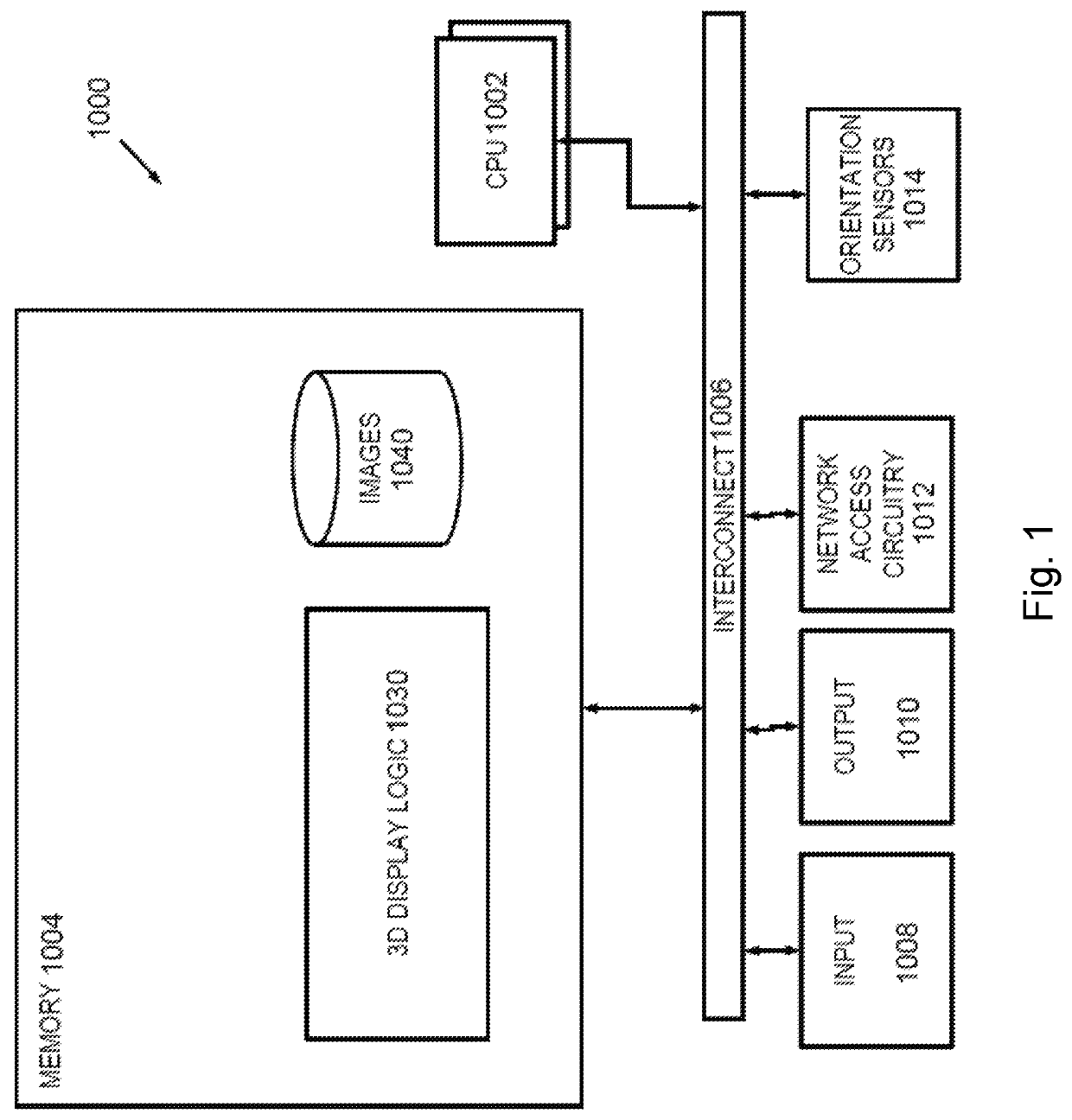
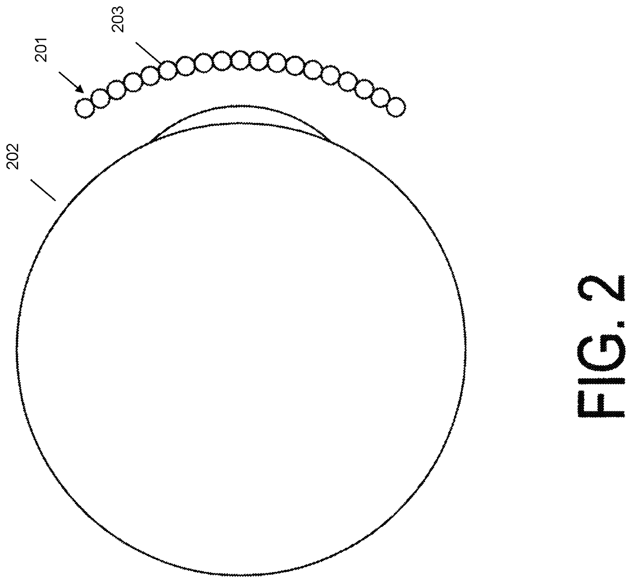
[0019]In accordance with the present invention, an embodiment provides a method and system of providing a high-resolution near-eye display that is simultaneously capable of fast frame rates and very wide field of view. The system provides for a near-eye display without the large and cumbersome optical stack and other drawbacks found in conventional virtual reality headsets. The apparatus comprises a plurality of light-directing beads or mini-lenses. Reference in this application to the light-directing lenses may also be called light-directing beads or beads, or microlenses, or lenslets, for brevity and ease of reading. The beads shape may include fish-eye, spherical, ovoid, hexagonal, square, columnar, triangular, or like 3-dimensional shapes or like cross dimensional shapes. The term bead should not be construed as referring only to a spherical structure, although spherical beads may be an embodiment. Bead shapes in figures are illustrative only of an embodiment. Each of the disclo...


PUM


Abstract

An apparatus and system for a display screen for use in near-eye display devices. Small light emitting devices are placed behind a plurality of light-directing beads. The light emitting devices and light-directing beads for a display device and system placed in front of a user for near-eye display. This allows a user to experience near-eye display with greater resolution, wider field of view and faster frame rate. Other embodiments are described herein.

Description

CROSS-REFERENCE TO RELATED APPLICATIONS[0001]This application is a continuation-in-part of U.S. application Ser. No. 15 / 671,694, filed Aug. 8, 2017, the contents of which are incorporated by reference herein.FIELD OF THE INVENTION[0002]The present invention relates generally to display systems, and, more particularly, to display systems for near-eye displays such as virtual reality and augmented reality.BACKGROUND OF THE INVENTION[0003]Recently, there has been significant growth in the use and advancement of virtual reality, augmented reality, and similar near-eye products. Common virtual reality uses include video gaming, movies, amusement ride simulators, and the like. While the popularity is driven by entertainment, the products also serve functions in training and education. For example, virtual reality headsets may be used for flight simulation training, surgery simulation for physicians, technology in the traditional classroom to spark student interest in a subject, and the li...

Claims


Application Information

Patent Timeline
IPC IPC(8): G02B3/00G06F1/16
CPCG02B3/0006G02B2003/0093G06F1/163G02B27/0172G02B3/0037G06F3/011
Inventor MULLER, RICHARD A.WEINSTOCK, NEAL
Owner SOLIDDD
Why Eureka
Try Eureka