Piping joint and resin tube assembly

a technology of resin tube and piping joint, which is applied in the direction of fluid pressure sealing joints, hose connections, sleeves/socket joints, etc., can solve the problems of resin tube not being able to be fitted into the connection pipe, and the resin tube allowing the weight reduction has no flexibility

Active Publication Date: 2022-03-01
SANOH IND CO LTD
View PDF14 Cites 0 Cited by
  • Summary
  • Abstract
  • Description
  • Claims
  • Application Information

AI Technical Summary

Benefits of technology

[0017]According to an aspect of the present invention, a resin tube can be connected to a connection pipe for flexible hose connection as well.

Problems solved by technology

However, the resin tube allowing the weight reduction has no flexibility whereas the rubber hose is flexible, and thus the resin tube cannot be fitted into the connection pipe as it is.

Method used


Image

  • Piping joint and resin tube assembly
  • Piping joint and resin tube assembly
  • Piping joint and resin tube assembly

Examples


Embodiment Construction

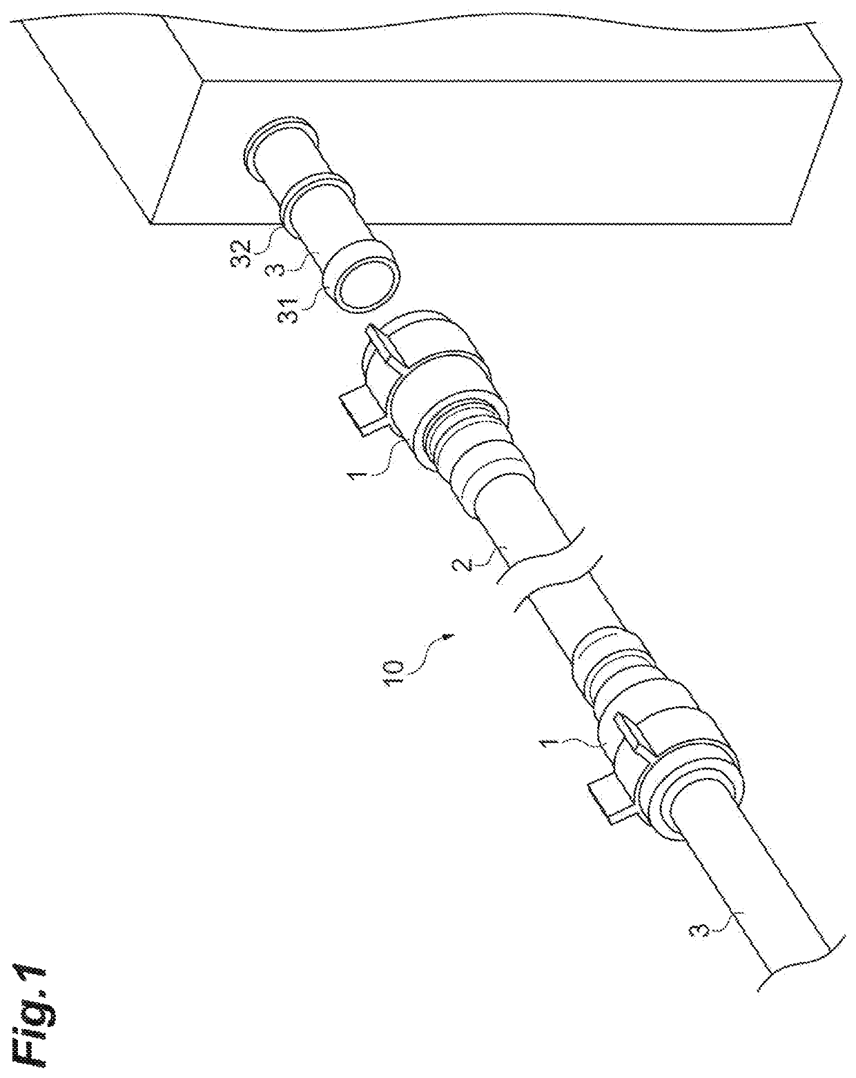
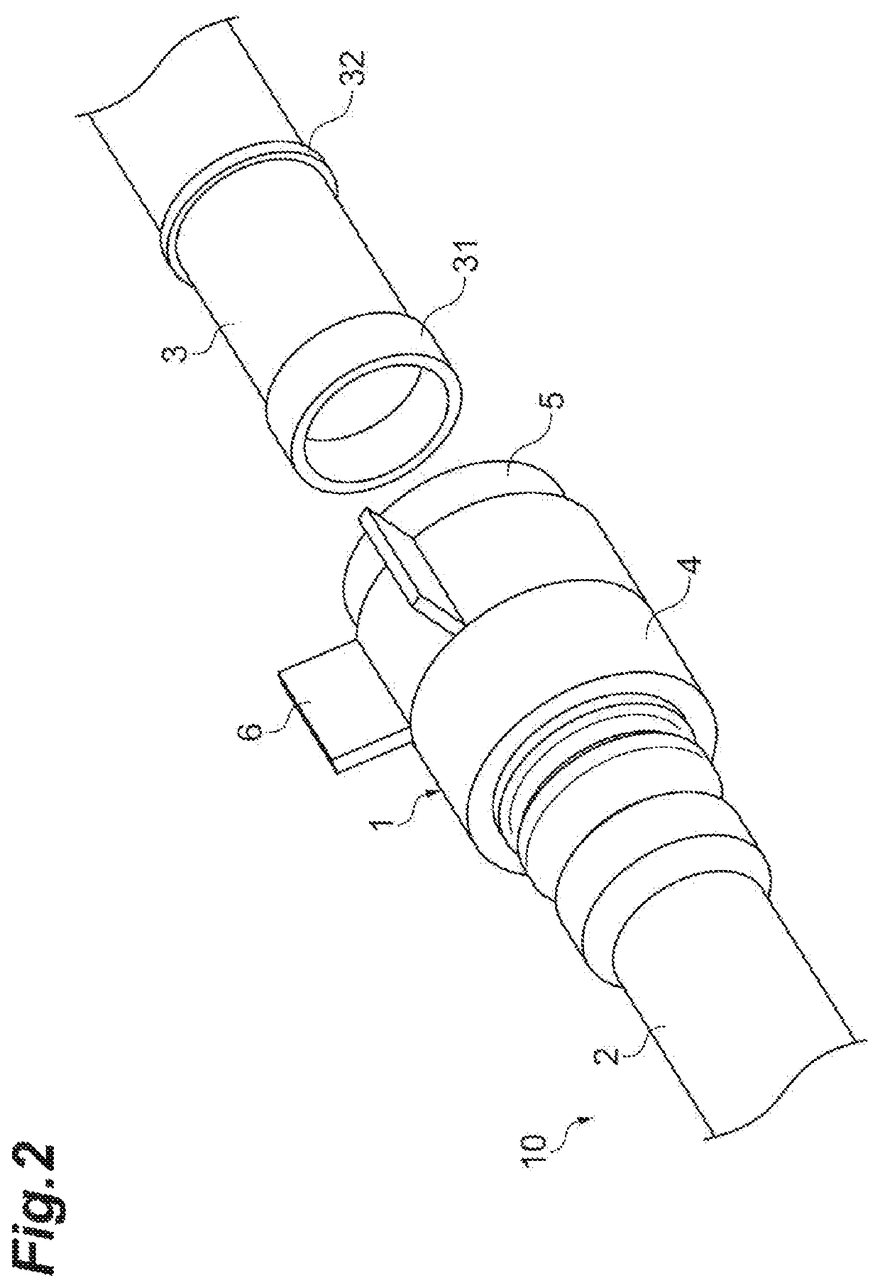
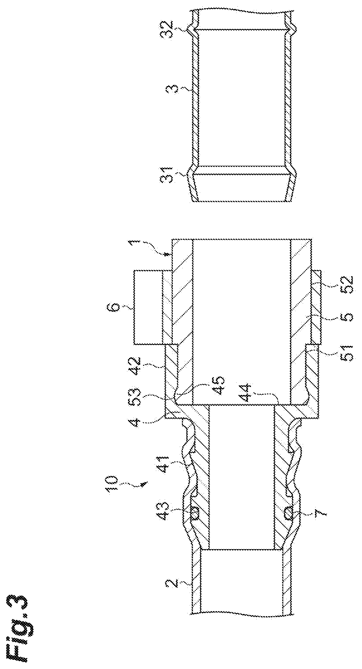
[0027]Hereinafter, a piping joint and a resin tube assembly according to an embodiment will be described with reference to accompanying drawings. In the present embodiment, the same or corresponding elements in the drawings are denoted by the same reference numerals with redundant description omitted.

[0028]As illustrated in FIGS. 1 to 3, a piping joint 1 according to the present embodiment is a joint for connecting a resin tube 2 to a connection pipe 3. The piping joint 1 and the resin tube 2 constitute a resin tube assembly 10.

[0029]The resin tube 2 is used for weight reduction and as a substitute for a flexible hose having flexibility such as a rubber hose. The resin tube 2 is formed of a resin lighter than the flexible hose. Although the resin that forms the resin tube 2 is not particularly limited, a polyamide-based resin, a polyphenylene sulfide resin, and the like can be used from the viewpoint of weight reduction.

[0030]The connection pipe 3 is a pipe used for flexible hose co...


PUM

PropertyMeasurementUnit
flexibleaaaaaaaaaa
flexibilityaaaaaaaaaa
shapeaaaaaaaaaa

Abstract

A piping joint connects a resin tube to a connection pipe having a protrusion formed on an outer peripheral surface of a distal end portion of the connection pipe. The piping joint includes a housing press-fitted into the resin tube and an elastically extendable and contractible seal member into which the connection pipe is inserted such that sealing is performed between the connection pipe and the seal member. The housing has a first housing portion positioned in one end portion and having an outer peripheral surface side press-fitted into the resin tube and a second housing portion positioned in the other end portion. The seal member has a first seal portion inserted on an inner peripheral surface side of the second housing portion.

Description

CROSS-REFERENCE TO RELATED APPLICATIONS[0001]This application is a U.S. National Stage entry of PCT Application No: PCT / JP2018 / 004235 filed Feb. 7, 2018, which claims priority to Japanese Patent Application No. 2017-032423, filed Feb. 23, 2017, the contents of which are incorporated herein by reference.TECHNICAL FIELD[0002]An aspect of the present invention relates to a piping joint connecting a resin tube to a connection pipe having a protrusion formed on an outer peripheral surface of a distal end portion of the connection pipe and a resin tube assembly provided with the piping joint.BACKGROUND ART[0003]In an automotive cooling circuit of the related art or the like, a flexible hose having flexibility, such as a rubber hose, is connected to a connection pipe having a protrusion formed on an outer peripheral surface of a distal end portion of the connection pipe (see, for example, Patent Literature 1). The protrusion is also called a bulge shape, a curl shape, and so on and has a f...

Claims


Application Information

Patent Timeline
Patent Type & Authority Patents(United States)
IPC IPC(8): F16L33/10F16L21/02F16L37/084F16L17/02F16L21/08F16L37/05
CPCF16L21/02F16L37/084F16L17/02F16L21/08F16L37/05F16L2201/10F16L33/30F16L37/04
Inventor OBA, FUMINORIKAMAZUKA, UKYOSHEN, JUNJIEYAMAGUCHI, MASASHI
Owner SANOH IND CO LTD
Why Eureka
Try Eureka