
Method and circuit arrangement for unlocking a charging plug in an emergency designed for a charging station for charging an electric energy storage of an electric vehicle

a charging plug and charging station technology, applied in charging stations, electric devices, transportation and packaging, etc., can solve problems such as negative impact, capacitors are subjected, and limited service li

Active Publication Date: 2022-03-22
BENDER SA
View PDF40 Cites 11 Cited by
  • Summary
  • Abstract
  • Description
  • Claims
  • Application Information

AI Technical Summary

Benefits of technology

This patent describes a method and circuit arrangement for safely unlocking a charging plug in an emergency. The technology uses a step-up converter to supply energy to the electric-motor drive unit, reducing the size and cost of the required capacitor. The emergency unlocking controller takes over controlling and monitoring the electric-motor drive unit during normal operation, eliminating the need for a separate control system. The controller also ensures safe electrical isolation of the charging plug by controlling the contactor upon unlocking in an emergency without aid from the superordinate locking controller.

Problems solved by technology

For the emergency unlocking to take place reliably, capacitors of large electric capacity are required—typically in the range of 20 mF to 50 mF—which has a negative impact.
A further disadvantage is that the contacts of the relay connecting the capacitor are subject to wear when switched on due to very high short-circuit currents and thus have only a limited service life.
Further disadvantages of the solutions to an emergency unlocking known from the state of the art are seen in the electric-motor drive unit being driven via two separate hardware motor controllers, one of which is activated during normal operation while the other is responsible for the emergency unlocking.

Method used


Image

  • Method and circuit arrangement for unlocking a charging plug in an emergency designed for a charging station for charging an electric energy storage of an electric vehicle

Examples


Embodiment Construction

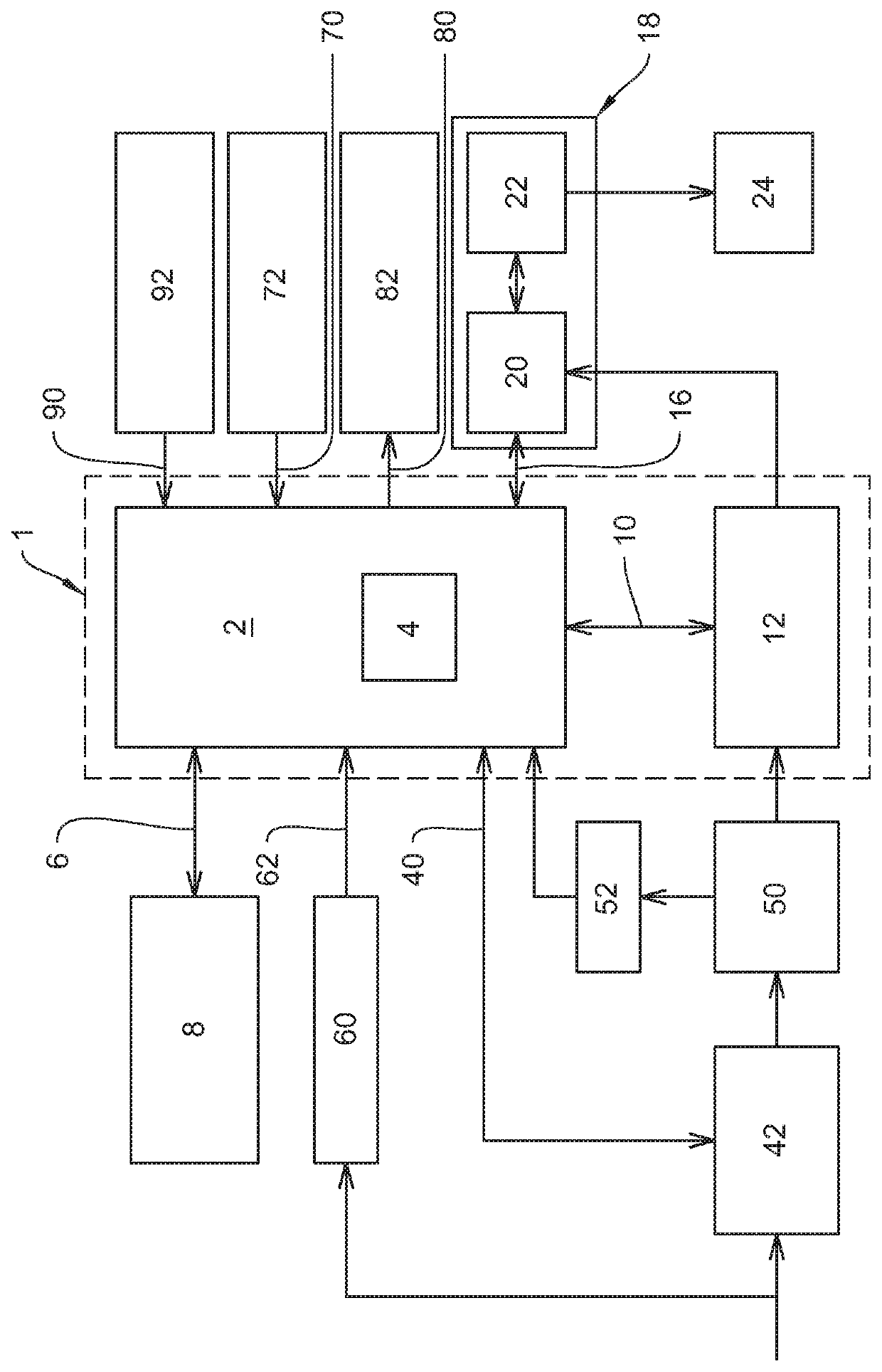
[0042]Circuit arrangement 1 comprises an emergency unlocking controller 2 which comprises a microcontroller 4. Emergency unlocking controller 2 further comprises a first communication interface 6 for transferring data using a superordinate locking controller 8. Besides the locking or unlocking commands received during normal operation from superordinate unlocking controller 8, emergency unlocking controller 2 can receive the following optional commands: specifications or different electric motors with motor parameters (controller times, current limitation), updates for the unlocking controller, activated / deactivated emergency unlocking, temperature thresholds and receipts for different temperature situations.

[0043]Besides transferring the locking state (locked / unlocked), diagnosis values such as electric voltages of the motor, supply voltages or intermediate voltages, temperatures or switching operations can optionally be transferred as data to superordinate locking controller 8 via...


PUM


Abstract

A method and a circuit arrangement for unlocking a charging plug in an emergency designed for a charging station for charging an electric energy storage of an electric vehicle, having a locking mechanism activated by an electric-motor drive unit. An emergency unlocking controller is a self-sufficient functional block in conjunction with a step-up converter for supplying the electric-motor drive unit with power, the input voltage of the step-up converter stepped up to the nominal voltage of the electric motor. A microcontroller controls and monitors the electric-motor drive unit and the step-up converter and for communicating with a superordinate locking controller generally disposed in the charging station. The step-up converter allows nearly the entire electric energy stored in the storage capacitor connected upstream of the step-up converter to be supplied to the electric-motor drive unit, whereby the motor can be operated at its required nominal voltage.

Description

[0001]This application claims the benefit of German patent application no. 10 2019 122 377.6 filed on Aug. 20, 2019, the disclosure of which is incorporated by reference.FIELD OF THE INVENTION[0002]The invention relates to a method and a circuit arrangement for unlocking a charging plug in an emergency designed for a charging station for charging an electric energy storage of an electric vehicle, the charging station comprising a locking mechanism which is activated by an electric-motor drive unit.BACKGROUND OF THE INVENTION[0003]With increasing demand for electromobility, it has become necessary to regularly charge the electric energy storage of electric vehicles. For conductive charging, the electric vehicle is connected to a charging station via a charging cable. A charging plug disposed on the charging cable is inserted into a charging socket at the charging station and locked there. This is achieved by means of a locking mechanism which is disposed in the charging station and i...

Claims


Application Information

Patent Timeline
Patent Type & Authority Patents(United States)
IPC IPC(8): B60L53/30B60L53/62B60L53/16
CPCB60L53/30B60L53/16B60L53/62B60L2270/32B60L53/60B60L3/0069B60L53/66B60L3/04B60L2240/527B60L53/305Y02T10/70Y02T10/7072Y02T90/12Y02T90/16Y02T90/14
Inventor MORICH, LARSFREITAG, STEFFENSCHLEITER, LEONIE
Owner BENDER SA
Learn More