Device and system for fluid flow measurement

a technology of fluid flow and measuring device, which is applied in the direction of flow control, liquid/fluent solid measurement, volume/mass flow by thermal effects, etc. it can solve the problem of rapid deterioration of thin wires used in sensors, and achieve the effect of preventing damage to the first portion of the exterior of the housing and increasing the accuracy of fluid flow measuremen

Active Publication Date: 2022-04-05
BAKER HUGHES ENERGY TECH UK LTD
View PDF34 Cites 2 Cited by
  • Summary
  • Abstract
  • Description
  • Claims
  • Application Information

AI Technical Summary

Benefits of technology

[0008]The housing provides an enclosing for the heating element, and may also enclose the detector. The housing therefore may provide protection for components of the device. It will, however, be appreciated that the housing may reduce the transfer of heat to a fluid. Such a reduction in the transfer of heat may result in an increase in heat required to be generated by the heating element in order to provide a corresponding sensitivity to change in transfer of heat arising due to differences in flow of the fluid. By providing a device in which thermal paths from the heating element are configured, it may be possible to reduce or avoid the need to increase the heat required to be generated by the heating element.
[0033]The housing may comprise a protective cage configured to prevent solid materials carried by the fluid from contacting the first region of the exterior of the housing. The protective cage may extend axially beyond a terminal end of the shell of the first and / or second sensor. As such, damage to the first portion of the exterior of the housing may be prevented.

Problems solved by technology

Hot wire sensor designs work reasonably well when used in gases, but may suffer from disadvantages when exposed to liquids.
For example, exposure to liquids can result in rapid deterioration of thin wires used in sensors.

Method used


Image

  • Device and system for fluid flow measurement
  • Device and system for fluid flow measurement
  • Device and system for fluid flow measurement

Examples


Embodiment Construction

[0050]Embodiments will now be described by way of example with reference to FIGS. 1 to 7.

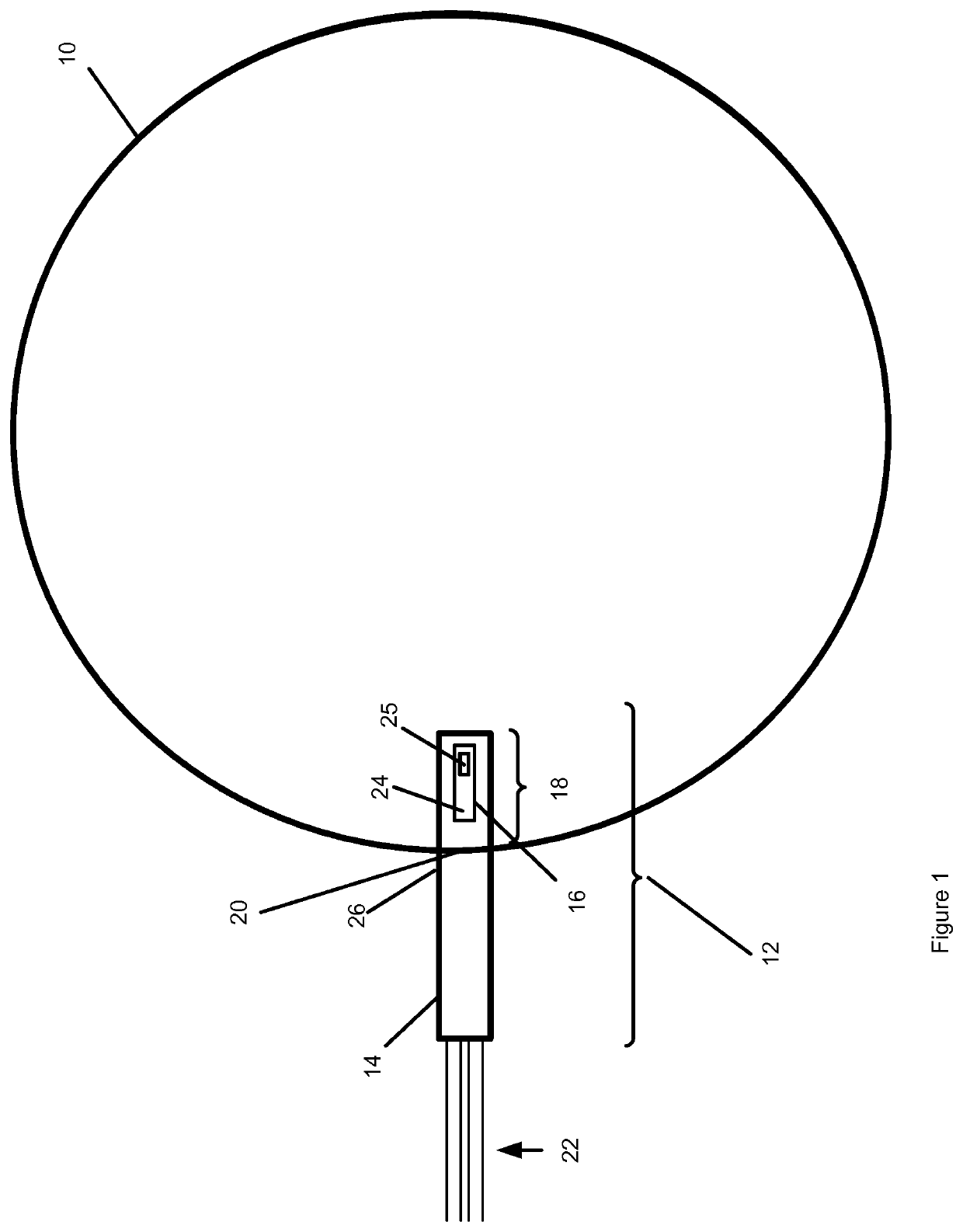
[0051]FIG. 1 illustrates a cross sectional view through a conduit 10 in which a sensor assembly 12 is provided for measuring flow of fluid in the conduit 10. The conduit 10 may be an oil or gas conduit 10 such as a surface pipeline or downhole tubing. Alternatively, conduit 10 could be any conduit suitable for transporting fluids and the sensor assembly could be used to measure the flow of different fluids such as blood, milk, water or chemicals in a number of industries from healthcare to power plants to the food industry.

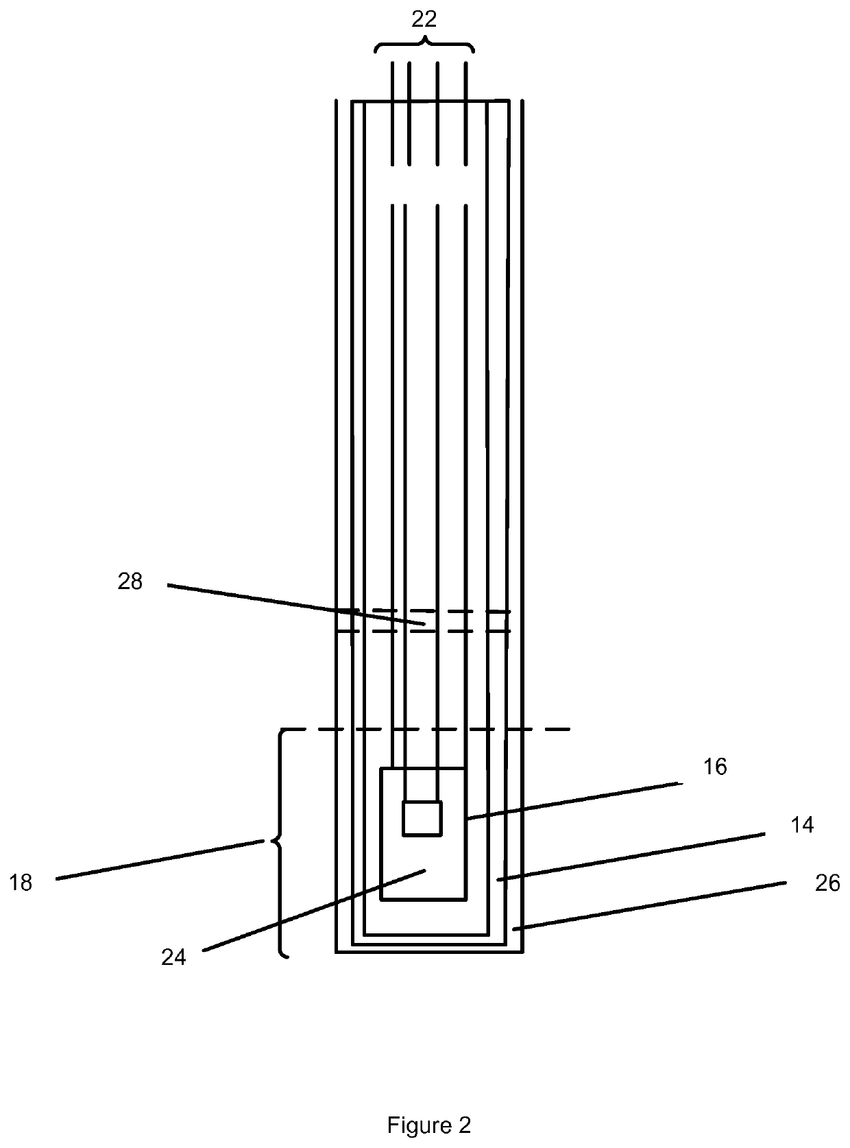
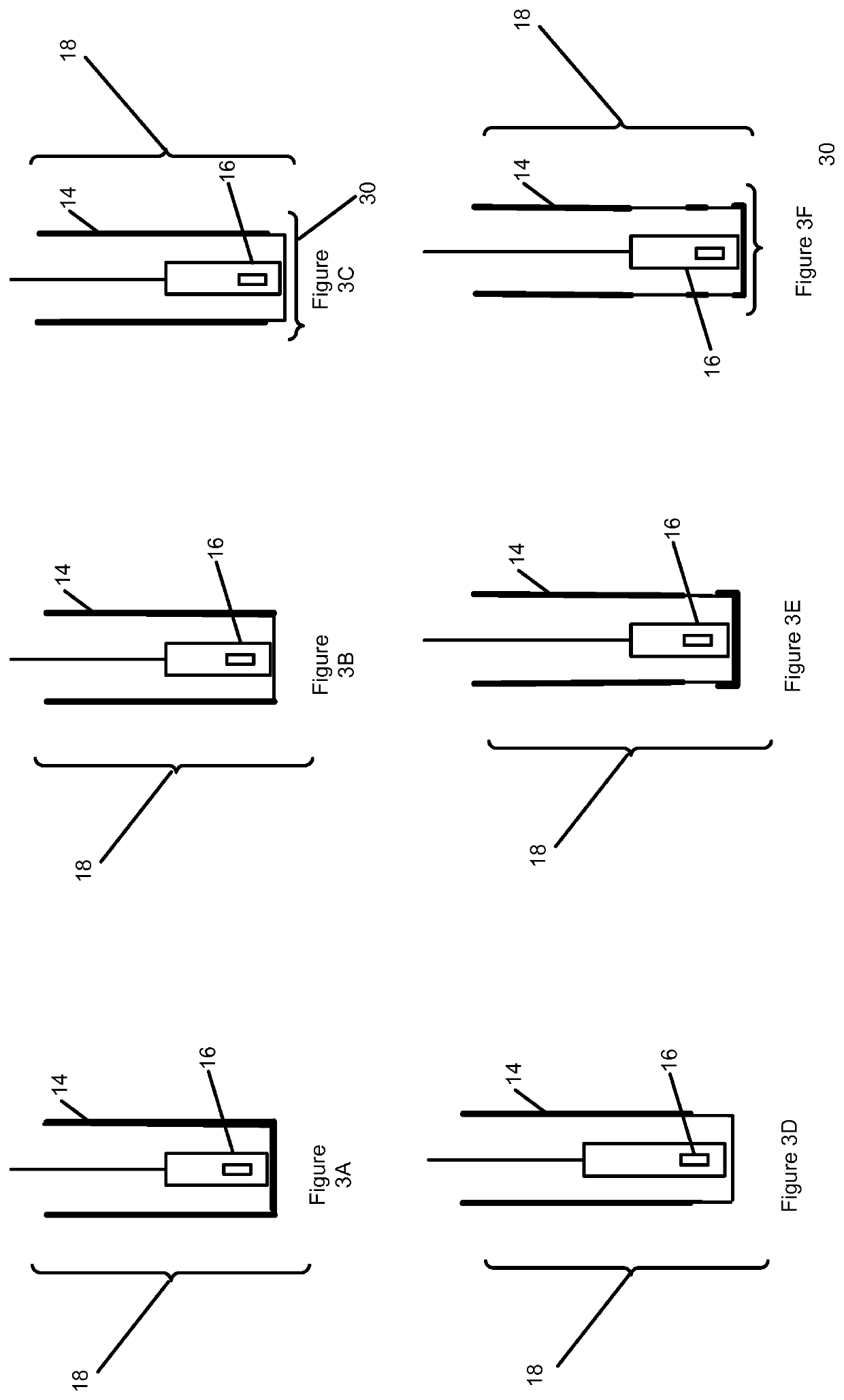
[0052]The sensor assembly 12 comprises a body or housing 14 housing a sensor 16. The housing 14 is configured to be inserted in the conduit 10 such that an external surface of an exposed portion 18 of the housing 14 is exposed to the fluid in the conduit 10. For example, conduit 10 may be provided with an opening 20 arranged to receive an assembly such as sensor assembly 12 an...


PUM


Abstract

A device for measuring the rate of flow of a fluid comprising. The device includes a heating element, a housing, and a detector. The heating element is located in an interior of the housing, the housing defining a first thermal path from the heating element to a first region of an exterior of the housing and a second thermal path from the heating element to a second region of the exterior of the housing. The detector is configured to detect a property associated with transfer of heat from the heating element to the exterior of the housing. The first thermal path has a first thermal conductivity and the second thermal path has a second thermal conductivity. The first thermal conductivity is greater than the second thermal conductivity. The first region of the exterior of the housing is smaller than the second region of the exterior of the housing.

Description

FIELD OF THE INVENTION[0001]The present disclosure relates to a device for measuring the rate of flow of fluids, and has application in the field of petrochemical flows, such as for example oil and gas fluid flows.BACKGROUND OF THE INVENTION[0002]The mass flow rate or flow rate of a fluid is an important quantity in many industrial applications. The mass flow rate or flow rate of a fluid is typically defined by the average velocity of the fluid multiplied by its mass density multiplied by the cross-sectional area of the conduit through which the fluid travels.[0003]One known technique for measuring mass flow rate or flow rate of a fluid is using the cooling effect of a fluid in contact with a heated element. For example, hot wire sensors have been used to measure both mass flow rate and flow rate using a pair or more of hot wires. Typical hot wire sensors use a tungsten or platinum wire with a diameter of the order of five microns held between two components of the order of 2 mm apa...

Claims


Application Information

Patent Timeline
Patent Type & Authority Patents(United States)
IPC IPC(8): F16K31/02G01F1/684G01F1/688G01F1/69G05D7/06
CPCG01F1/6842G01F1/684G01F1/6847G01F1/6888G01F1/69G05D7/0617G01F1/68
Inventor MAHALINGAM, SAKETHRAMAN
Owner BAKER HUGHES ENERGY TECH UK LTD
Why Eureka
Try Eureka