Convertible ducted fan engine

a ducted fan and convertible technology, applied in the direction of rotors, aircraft convertible vehicles, liquid fuel engines, etc., can solve the problems of complex reconfigurable drive systems, less than ideal separate and reconfigurable drive systems, and more susceptible to failure, so as to prevent relative rotation and prevent relative rotation

Active Publication Date: 2022-05-17
HYALTA AERONAUTICS INC
View PDF5 Cites 0 Cited by
  • Summary
  • Abstract
  • Description
  • Claims
  • Application Information

AI Technical Summary

Benefits of technology

[0011]The convertible ducted fan engine includes a fluid-propulsion configuration in which the mechanical fan rotates freely with respect to the shroud to produce thrust through fluid flow, and a drive-wheel configuration in which at least one of the blades in the plurality of blades is in contact with the shroud, thereby causing concurrent rotation of the shroud and mechanical fan when the mechanical fan rotates about the rotational axis.
[0026]An embodiment of the craft further includes the convertible engine having an electrical coil disposed on or in the shroud and the electrical coil is connected to a power source. A collar is concentrically located with respect to the outer shroud, the collar receiving at least a portion of a proximal body in a rotationally free relation. A first clutch is disposed between the collar and the proximal body. The first clutch can be engaged to prevent relative rotation between the collar and the proximal body. The proximal body is secured to a mounting arm at a first end and is in rotational communication with a distal body at a second end. The distal body is in mechanical communication with the plurality of blades and a second clutch is disposed between the proximal and distal bodies. The second clutch can be engaged to prevent relative rotation between the proximal and distal bodies. In addition, at least one blade in the plurality of blades has a magnetic component disposed proximate a free end of the blade. The electrical coil can be electrified to cause or prevent rotation of the plurality of blades with respect to the shroud, and the first and second clutches enable the ducted fan engine to operate as a propulsion engine or a drive wheel.

Problems solved by technology

Such vehicles, however, require separate or reconfigurable drive systems.
Both separate and reconfigurable drive systems are less than ideal.
Reconfigurable drive systems can be complex and thus more susceptible to failure, while separate drive systems occupy twice the space and require twice the fuel compared to a single drive system.

Method used


Image

  • Convertible ducted fan engine
  • Convertible ducted fan engine
  • Convertible ducted fan engine

Examples


Embodiment Construction

[0045]In the following detailed description of the preferred embodiments, reference is made to the accompanying drawings, which form a part thereof, and within which are shown by way of illustration specific embodiments by which the invention may be practiced. It is to be understood that other embodiments may be utilized and structural changes may be made without departing from the scope of the invention.

Glossary of Claim Terms

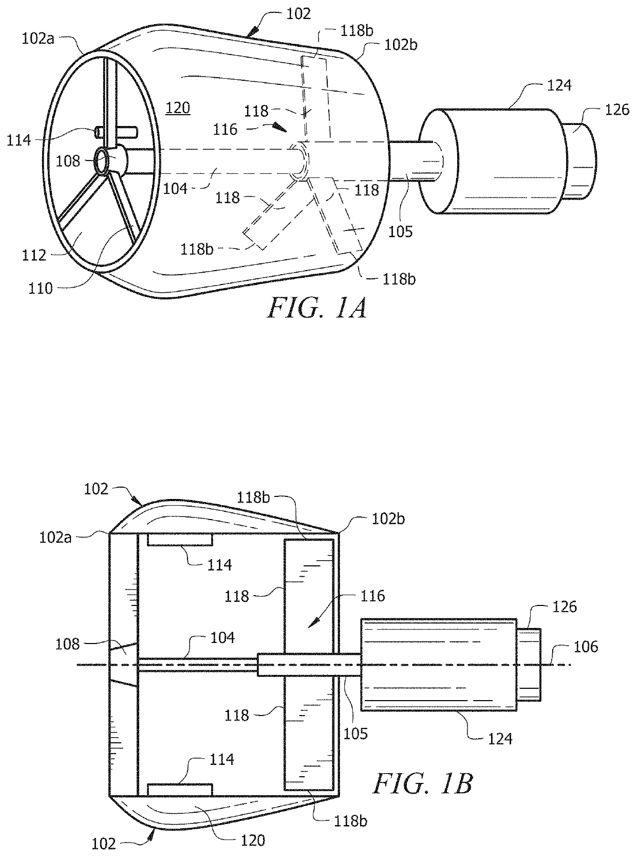
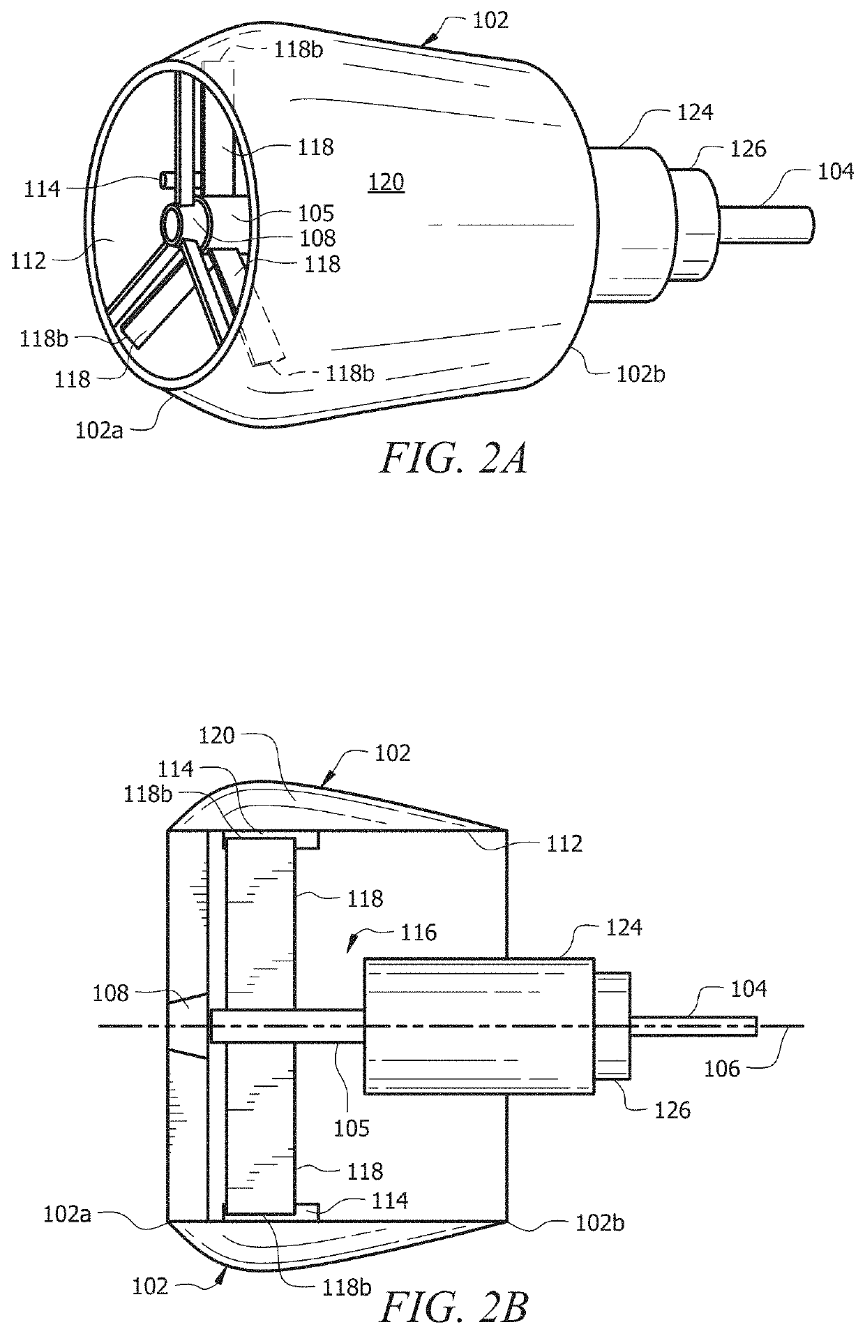
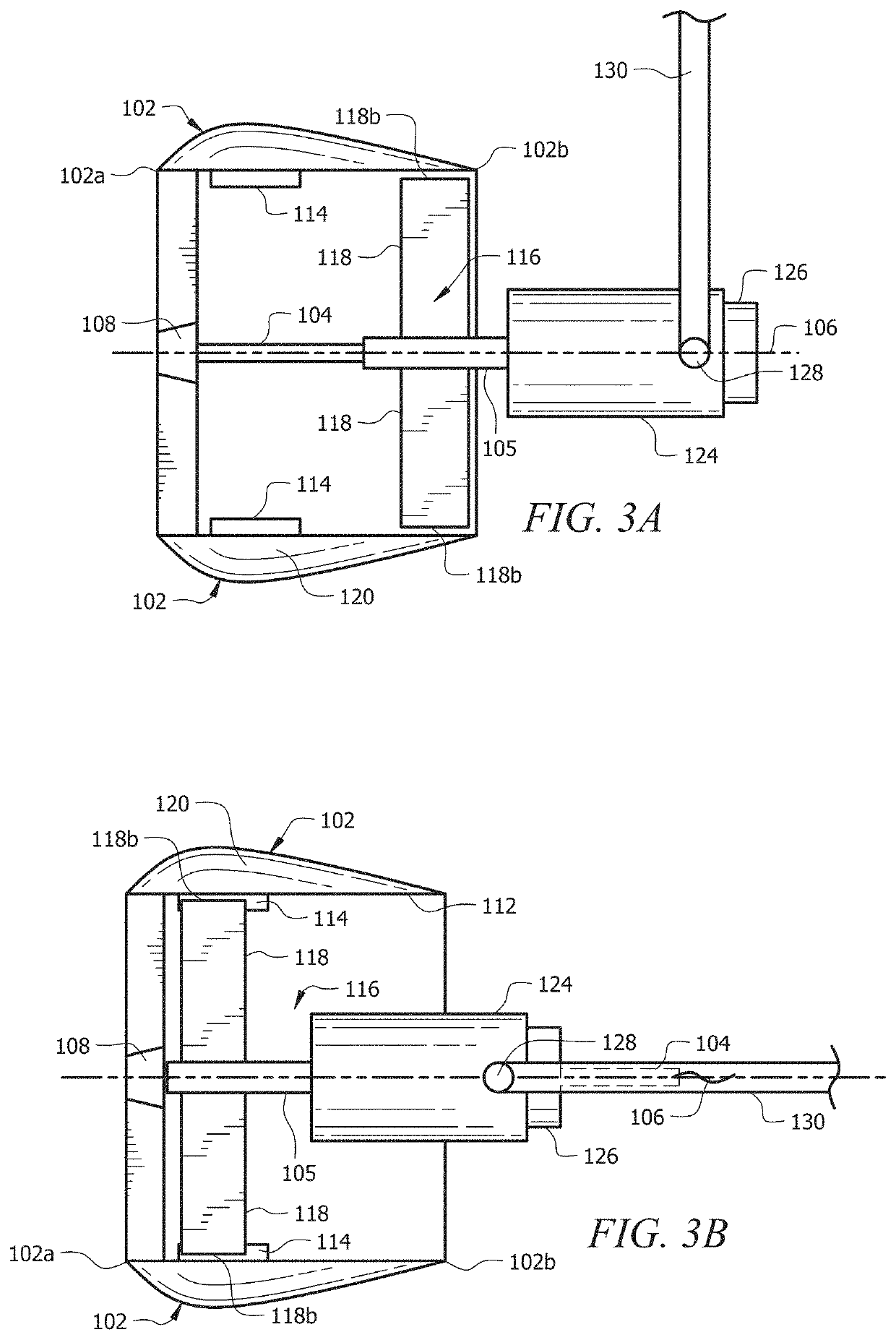
[0046]Drive-Wheel Configuration: is a configuration where the shroud is configured to rotate about the rotational axis.

[0047]Fluid-Propulsion Configuration: is a configuration where the mechanical fan is configured to rotate about the rotational axis.

[0048]Shroud: is a structure intended to at least partially surround the mechanical fan.

[0049]Tread: is a material disposed on the external surface of the shroud that is intended to increase traction between the shroud and the shroud-contacting surface.

[0050]The present invention includes a convertible ducted fan ...


PUM


Abstract

A convertible ducted fan engine having a shroud, a drive shaft connected to a mechanical fan, and a rotational drive motor configured to rotate the mechanical fan. An embodiment includes a linear drive motor configured to translate the drive shaft and mechanical fan in a direction parallel to a longitudinal axis of the shroud. The convertible ducted fan engine includes a fluid-propulsion configuration in which the mechanical fan rotates freely with respect to the shroud to produce thrust through fluid flow, and a drive-wheel configuration in which the shroud rotates about the rotational axis.

Description

CROSS-REFERENCE TO RELATED APPLICATIONS[0001]This nonprovisional application is a continuation-in-part of and claims priority to nonprovisional application Ser. No. 15 / 209,383, entitled “CONVERTIBLE DUCTED FAN ENGINE,” filed Jul. 13, 2016 by the same inventor.BACKGROUND OF THE INVENTION1. Field of the Invention[0002]This invention relates, generally, to a ducted fan engine. More specifically, it relates to a ducted fan engine capable of converting between a typical fluid-propulsion configuration and a friction-based drive-wheel configuration.2. Brief Description of the Prior Art[0003]The current state of the art includes a plurality of distinct thrust producing engines. Typically, these engines are single purpose drive systems designed around the type of vehicle (e.g. ground vehicles, watercraft, or aircraft) on which they are intended to operate. For example, a drive-wheel—a tire connected to a rotating shaft—provides propulsion for land vehicles, while propellers or turbines are c...

Claims


Application Information

Patent Timeline
Patent Type & Authority Patents(United States)
IPC IPC(8): F01D15/00F01D25/24B64C25/66B64C25/34B64C25/40B64C37/00B60F5/02F01D7/00B60F3/00F04D29/32F04D29/52B64C39/02
CPCF01D15/00B60F3/0007B60F5/02B64C25/34B64C25/405B64C25/66B64C37/00F01D7/00F01D25/24F04D29/326B60F2301/04B64C39/024B64C2201/027F04D29/325F04D29/522F05D2220/70F05D2240/14F05D2240/20B64C11/001B64D35/00B64U10/13
Inventor KEMPSHALL, SCOTT R.
Owner HYALTA AERONAUTICS INC
Why Eureka
Try Eureka