Apparatus for the aftertreatment of exhaust gases

an exhaust gas and aftertreatment technology, which is applied in the direction of mechanical equipment, engines, machines/engines, etc., can solve the problems of delay, non-optimal and difficulty or inability to regulate the exhaust gas stream flowing through the electrically heatable catalytic converter, etc., to achieve the effect of improving the heating of exhaust gas mass flow

Active Publication Date: 2022-05-24
VITESCO TECH GERMANY GMBH
View PDF33 Cites 0 Cited by
  • Summary
  • Abstract
  • Description
  • Claims
  • Application Information

AI Technical Summary

Benefits of technology

[0005]It is therefore an object of one aspect of the present invention to create an apparatus for exhaust gas aftertreatment that allows improved heating of the exhaust gas mass flow using an electrically heatable catalytic converter, and thus ensure faster reaching of the minimum temperature of the exhaust gas mass flow for adequate conversion of the exhaust gas at the respective catalytic converters.

Problems solved by technology

The disadvantage of the systems known from the prior art for electric heating of the exhaust gas mass flow of an internal combustion engine is here in particular that the exhaust gas stream flowing through the electrically heatable catalytic converter is difficult or impossible to regulate.
The mass flow through the electrically heated catalytic converter is thus determined solely by the respective operating situation of the internal combustion engine, for which reason, in particular for high exhaust gas mass flows, it may occur that a non-optimal heating of the exhaust gas mass flow takes place, whereby a time delay may occur until an adequate conversion of the exhaust gas is achieved in the catalytic converters of the exhaust gas aftertreatment unit.

Method used


Image

  • Apparatus for the aftertreatment of exhaust gases
  • Apparatus for the aftertreatment of exhaust gases
  • Apparatus for the aftertreatment of exhaust gases

Examples


Embodiment Construction

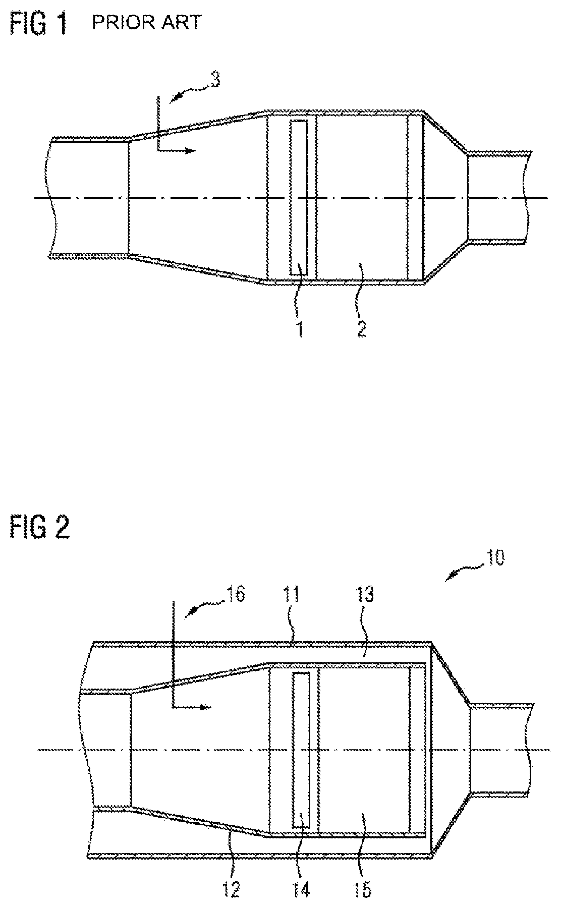
[0039]FIG. 1 is a sectional view through an apparatus for exhaust gas aftertreatment. This is formed by a housing with regions of different diameters. A device 1 for heating the exhaust gas flow is arranged inside the housing, and downstream thereof a catalytic converter 2, which serves for aftertreatment of exhaust gases. In addition, the apparatus may have elements for the addition of operating media 3, in order for example to introduce a watery urea solution or fuel into the apparatus.

[0040]The apparatus shown in FIG. 1 is in particular characterized in that the entire exhaust gas stream, which flows through the apparatus from left to right, flows completely through the heating element 1 and the downstream catalytic converter 2. If the exhaust gas mass flow does not have the temperature necessary for heating the catalytic converter 2 to a temperature sufficient for its operation, the entire exhaust gas mass flow must be heated by the heating element, so as also to heat the cataly...


PUM


Abstract

An apparatus for aftertreatment of exhaust gases of an internal combustion engine, with a housing through which the exhaust gas can flow from an inlet to an outlet, a flow path spatially delimited in a radial direction and through which gases can flow in an axial direction arranged inside the housing, a catalytic converter in the flow path, and a heating element arranged in the flow path for electrically heating the exhaust gas. An annular gap through which gases can flow is formed between the flow path and the inner wall of the housing. The distribution of the exhaust gas mass flow between the flow path and the annular gap is influenced by a control element.

Description

CROSS REFERENCE TO RELATED APPLICATIONS[0001]This is a U.S. national stage of Application No. PCT / EP2019 / 057525 filed Mar. 26, 2019. Priority is claimed on German Application No. DE 10 2018 204 903.3 filed Mar. 29, 2018 the content of which is incorporated herein by reference.BACKGROUND OF THE INVENTION1. Field of the Invention[0002]The invention relates to an apparatus for aftertreatment of exhaust gases of an internal combustion engine, with a housing through which the exhaust gas can flow from an inlet to an outlet, a flow path arranged inside the housing, which is spatially delimited in a radial direction and through which gases can flow in an axial direction, at least one catalytic converter arranged in the flow path for catalytic conversion of the exhaust gas, and at least one heating element for electrically heating the exhaust gas arranged in the flow path and through which the exhaust gas can flow.2. Description of Related Art[0003]For faster heating of exhaust gas mass flo...

Claims


Application Information

Patent Timeline
Patent Type & Authority Patents(United States)
IPC IPC(8): F01N3/10F01N3/20F01N3/035
CPCF01N3/2013F01N3/035F01N2240/16F01N2240/36F01N2470/24F01N2610/02F01N3/2053F01N2260/14F01N2410/03
Inventor HOLZ, OSWALDILLHARDT, PETER
Owner VITESCO TECH GERMANY GMBH
Why Eureka
Try Eureka