Probe head for high frequency signal test and medium or low frequency signal test at the same time

a technology of probe head and probe card, which is applied in the direction of electrical testing, measurement devices, instruments, etc., can solve the problems of long length, difficult to thin spring probes, and test machines long in length

Active Publication Date: 2022-05-31
MPI CORP
View PDF2 Cites 0 Cited by
  • Summary
  • Abstract
  • Description
  • Claims
  • Application Information

AI Technical Summary

Benefits of technology

[0006]The present invention has been accomplished in view of the above-noted circumstances. It is an objective of the present invention to provide a probe head which is adapted for high frequency signal test and medium or low frequency signal test at the same time, preventing probe cards from too complicated circuit design and meeting the requirements of fine pitch and high frequency testing at the same time.
[0009]It is another objective of the present invention to provide a probe head which is adapted for high frequency signal test and medium or low frequency signal test at the same time, preventing probe cards from too complicated circuit design, meeting the requirements of fine pitch and high frequency testing at the same time, and being able to perform high frequency signal test through a testing machine.
[0011]In other words, this probe head is similar to the above-described probe head, but they are primarily different in that the electrically conductive layer of this probe head partially extends to the outside of the probe seat. Besides, this probe head is not used in loopback test, thereby unlimited to have at least two second spring probes. As a result, the electrically conductive layer of this probe head can be connected to a main circuit board of the probe card, so that the second spring probe can be electrically connected with a testing machine through the electrically conductive layer and the main circuit board. Alternatively, the electrically conductive layer may be directly connected to the testing machine, so that the second spring probe can be electrically connected with the testing machine through the electrically conductive layer. In this way, the second spring probe and the electrically conductive layer can transmit high frequency signal between a DUT and the testing machine for performing high frequency signal test through the testing machine instead of high frequency signal loopback test. Therefore, this probe head can satisfy the high frequency testing requirement differing from that the above-described probe head can satisfy.

Problems solved by technology

However, because of limitations of testing machines, cost considerations or probes that are too long in length to enable high frequency testing, current vertical probe cards (also referred to as VPCs) mainly perform loopback test by some of the probes in the probe card for high frequency testing.
However, considering electrical properties, mechanical properties, force, operating stroke, lifetime and so on, it is difficult to make the spring probe thin when it is short and it is difficult to make it short when it is thin.
In other words, the requirements of fine pitch and high frequency testing are difficult to be satisfied at the same time by a same spring probe.
Such probe card is relatively more complicated in circuit design, and the probes should be sized to meet the requirement of high frequency testing, thereby difficult to meet the requirement of fine pitch.
Therefore, even with the aforementioned switch circuit, it is still difficult to apply the same probe to high frequency testing and medium or low frequency testing.
Such testing mode may not satisfy the testing requirement and thereby still needs improvement.

Method used


Image

  • Probe head for high frequency signal test and medium or low frequency signal test at the same time
  • Probe head for high frequency signal test and medium or low frequency signal test at the same time
  • Probe head for high frequency signal test and medium or low frequency signal test at the same time

Examples


Embodiment Construction

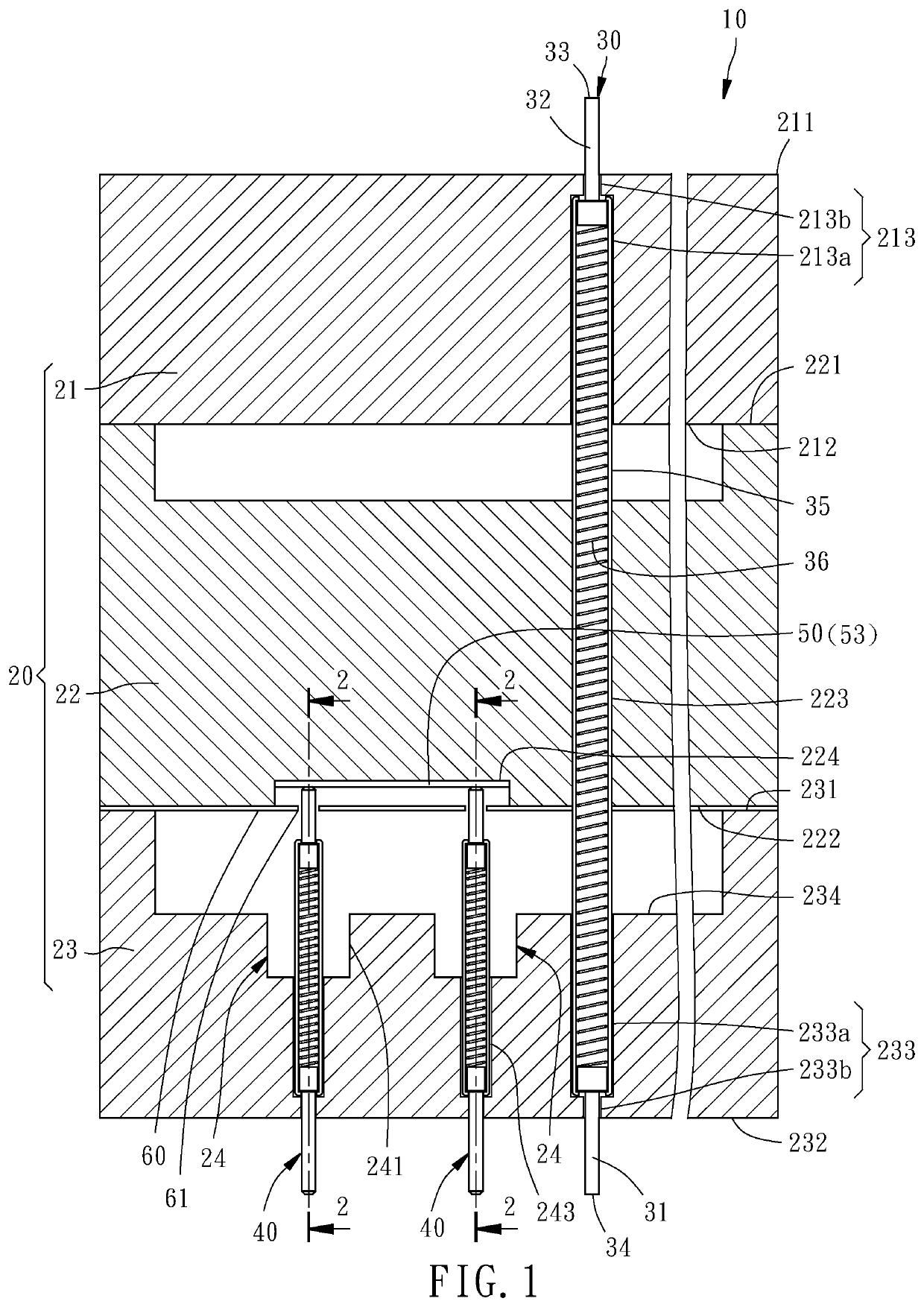
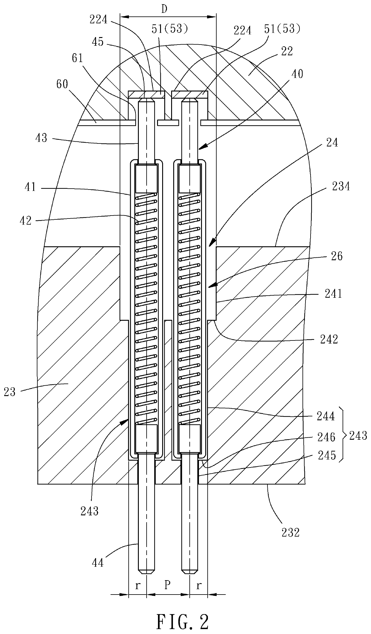
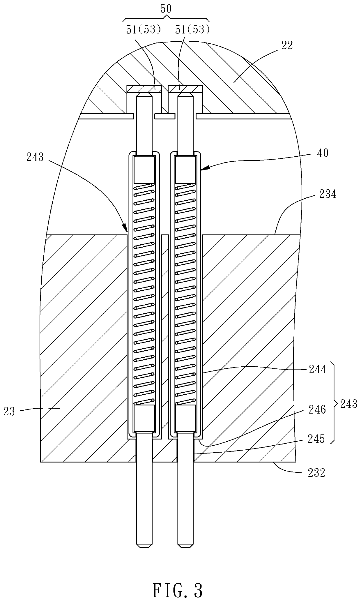
[0030]First of all, it is to be mentioned that same reference numerals used in the following embodiments and the appendix drawings designate same or similar elements or the structural features thereof throughout the specification for the purpose of concise illustration of the present invention. Besides, when it is mentioned that an element is disposed on another element, it means that the former element is directly disposed on the latter element, or the former element is indirectly disposed on the latter element through one or more other elements between aforesaid former and latter elements. When it is mentioned that an element is directly disposed on another element, it means that no other element is disposed between the two elements. It should be noticed that for the convenience of illustration, the components and the structure shown in the figures are not drawn according to the real scale and amount, and the features mentioned in each embodiment can be applied in the other embodi...


PUM

PropertyMeasurementUnit
frequencyaaaaaaaaaa
electrically conductiveaaaaaaaaaa
lengthaaaaaaaaaa

Abstract

A probe head includes a probe seat having upper, middle and lower dies, an electrically conductive layer inside the probe seat, a first spring probe penetrating through the probe seat, and at least two shorter second spring probes penetrating through the lower die in a way that top ends of the second spring probes are located inside the probe seat and abutted against the electrically conductive layer. Another probe head includes the aforesaid probe seat, an electrically conductive layer partially inside the probe seat and partially outside the probe seat, a first spring probe penetrating through the probe seat, and a shorter second spring probe penetrating through the lower die in a way that a top end of the second spring probe is located inside the probe seat and abutted against the electrically conductive layer. As such, fine pitch requirement and different high frequency testing requirements are fulfilled.

Description

CROSS REFERENCE TO RELATED APPLICATIONS[0001]This non-provisional application claims the benefit under 35 U.S.C. § 119(e) to U.S. Provisional Application No. 62 / 887,232, filed on Aug. 15, 2019; 62 / 896,716, filed on Sep. 6, 2019, and under 35 U.S.C. § 119(a) to Patent Application Nos. 108138536, filed in Taiwan on Oct. 25, 2019; 108145118, filed in Taiwan on Dec. 10, 2019; and 109120055, filed in Taiwan on Jun. 15, 2020, all of which are hereby expressly incorporated by reference into the present application.BACKGROUND OF THE INVENTION1. Field of the Invention[0002]The present invention relates generally to probe heads of probe cards and more particularly, to a probe head for high frequency signal test and medium or low frequency signal test at the same time.2. Description of the Related Art[0003]Due to market demand, the packaging and testing of integrated circuits (also referred to as ICs) are developed towards fine pitch and high frequency. However, because of limitations of testi...

Claims


Application Information

Patent Timeline
Patent Type & Authority Patents(United States)
IPC IPC(8): G01R1/067G01R1/073
CPCG01R1/06722G01R1/07378G01R1/06733G01R1/06772G01R1/07357G01R1/07314
Inventor YANG, CHIN-TIENYANG, HUI-PINHSIEH, SHANG-JUNGCHEN, TSUNG-YICHEN, YU-HAOLYU, JHIN-YING
Owner MPI CORP
Why Eureka
Try Eureka