Combined convector

a convector and convector technology, applied in the field of convectors, can solve the problems of reducing the performance of the cooler, requiring expensive maintenance, and people's risk of lethal infections, and achieves the effects of reducing consumption, reducing maintenance costs, and increasing efficiency

Active Publication Date: 2022-06-21
FRIGEL FIRENZE SPA
View PDF34 Cites 0 Cited by
  • Summary
  • Abstract
  • Description
  • Claims
  • Application Information

AI Technical Summary

Benefits of technology

[0014]More in particular, an important object of the present invention is to provide a convector for air cooling of a fluid flowing in a pipe, suitable to make the process fluid achieve low temperatures with reduced water consumption with respect to the evaporative coolers.
[0064]humidifying said air flow, inside at least one adiabatic or substantially adiabatic chamber, with vaporized or atomized water, said air flow being suitable to invest said vaporized or atomized water, before investing the heat exchanger, to decrease the air flow temperature,

Problems solved by technology

However, these coolers are subject to some problems like deposits and / or corrosion, that quickly degrade the performances of the coolers and require expensive maintenance; in fact, the evaporating water leaves, on the tube bundle and on the fins, its salt content, usually limescale and other salts.
Moreover, there are also problems linked to the dispersion into air of sprays that could involve a risk of lethal infections for people (e.g. Legionnaires' disease).
A limit of the adiabatic coolers is that, given the same cooling capability, the water consumption is higher (significantly higher in systems without adiabatic chamber): water that does not evaporate inside the air flow falls inside a collection basin; then, it can be discharged and not recovered, or it can be recovered in an accumulation tank and then supplied again to the humidifying packs; however, in systems with water recovery it is necessary to perform the so-called blow-down, i.e. it is necessary to discharge a certain percentage of recirculation water to avoid continuous increase in salt content like in a usual evaporative tower.

Method used


Image

  • Combined convector
  • Combined convector
  • Combined convector

Examples


Embodiment Construction

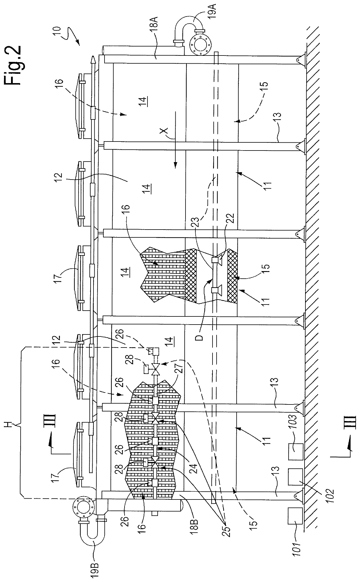
[0075]With reference to the above cited figures, a convector for air cooling of a fluid flowing in a tube, according to the invention, is indicated as a whole with number 10.

[0076]This convector 10 is comprised of five modules 11, connected in series. Each module 11 comprises an outer case 12 provided with supports 13 for resting on the ground and with walls 14.

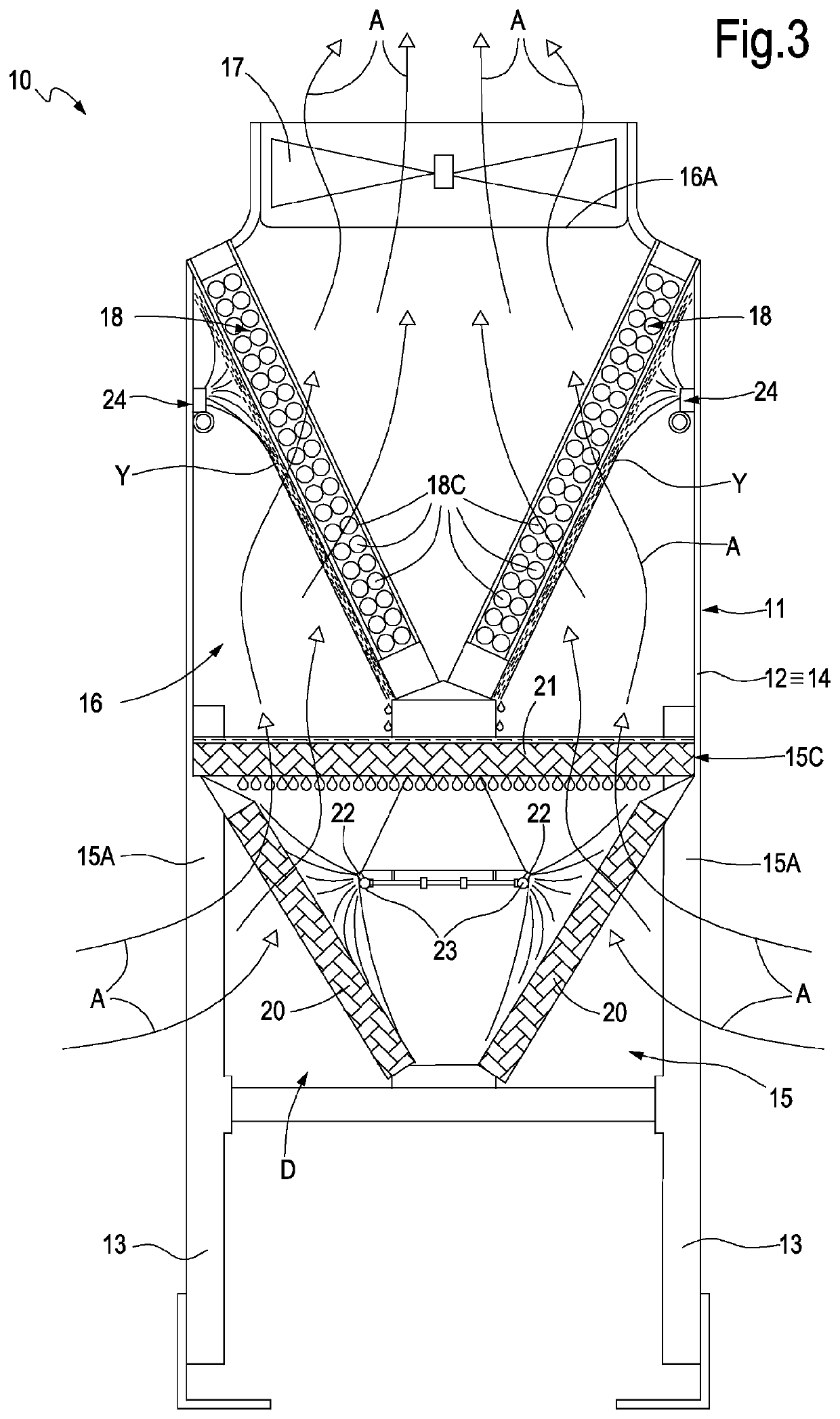
[0077]Each module 11 substantially defines two chambers, a lower chamber 15 and an upper chamber 16, defined directly above the lower chamber 15.

[0078]The lower chamber 15 has side inlets 15A (see FIG. 3) (and / or inlets in the chamber base) so that the air (indicated by the letter a) can enter from the outer environment. The upper chamber 16 has an upper outlet 16A, with which fan means are associated, for example a fan with vertical axis 17, to allow the air coming from the side inlets 15A to exit, forced by the fan. Between the lower chamber 15 and the upper chamber 16 passages are defined to allow the air A to flow through...


PUM

PropertyMeasurementUnit
temperatureaaaaaaaaaa

Abstract

A convector for air cooling of a fluid flowing in a pipe, comprising: a path for a cooling air flow comprising an inlet from and an outlet towards the environment, a heat exchange section comprising at least one tube bundle defining a heat exchange surface, said section being provided in said path for the air flow, fan means producing said air flow along said path, so that said air flow externally invests said tube bundle on said; heat exchange surface, a humidifying section arranged in said path, upstream of said heat exchange section, where water is atomized to be invested by the air flow, characterized by comprising a wetting device for wetting directly with water a portion of the heat exchange surface of said tube bundle to further cool said portion of tube bundle.

Description

TECHNICAL FIELD[0001]The present invention relates to a convector for air cooling of a fluid flowing in a pipe.STATE OF THE ART[0002]Nowadays, the convectors currently used for cooling of process fluids, also known as coolers, can be subdivided into the following types, according to the different operation modes: i) dry, ii) evaporative, and iii) adiabatic coolers.[0003]Dry-coolers are air coolers, i.e. heat exchangers with tube bundle, wherein the process fluid flows inside finned tubes and is cooled by means of air that, forced by one or more fans, flows at room temperature, without mains water consumption. The cooling capability of these coolers depends on the temperature difference between air and fluid as well as on the airflow. The temperature at which the process fluid exits the convector is limited by the dry-bulb temperature of ambient air.[0004]Evaporative coolers are air coolers, i.e. heat exchanger with finned tube bundle, wherein a nozzle ramp atomizes, under high press...

Claims


Application Information

Patent Timeline
Patent Type & Authority Patents(United States)
IPC IPC(8): F28D5/02F28F19/01F28C3/08F28F19/02
CPCF28D5/02F28C3/08F28F19/01F28F19/02F28F2245/02F28F25/08F28F25/06
Inventor STRUMENTI, FRANCESCODORIN, FILIPPO
Owner FRIGEL FIRENZE SPA
Why Eureka
Try Eureka