
Display panel

a display panel and panel technology, applied in the direction of identification means, instruments, non-linear optics, etc., can solve the problem of the most space-saving contact structure of the display panel, and achieve the effect of preventing the issue of impedance mismatch

Active Publication Date: 2022-06-28
AU OPTRONICS CORP
View PDF5 Cites 0 Cited by
  • Summary
  • Abstract
  • Description
  • Claims
  • Application Information

AI Technical Summary

Benefits of technology

[0004]Accordingly, the invention provides a display panel that may prevent the issue of impedance mismatch to signal lines in a peripheral region under the premise of high resolution and narrow frame.
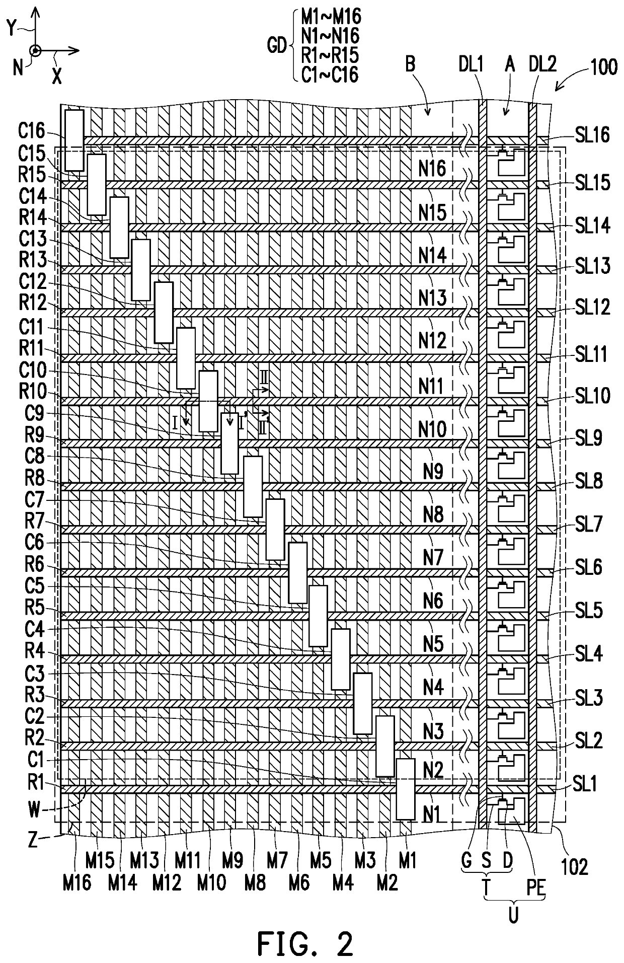
[0006]Based on the above, in the display panel of the invention, the gate driving circuit disposed in the peripheral region in the pixel array substrate of the display panel includes the plurality of first signal lines arranged along the first direction and extended along the second direction, the plurality of second signal lines extended along the first direction, the plurality of dummy signal lines extended along the first direction, and the plurality of contact structures disposed corresponding to the plurality of first signal lines, the plurality of second signal lines and the plurality of dummy signal lines, wherein each of the plurality of first signal lines is electrically connected to one corresponding second signal line via one corresponding contact structure, each of the plurality of dummy signal lines is electrically connected to one corresponding second signal line via one corresponding contact structure, and each of the plurality of second signal lines is respectively electrically connected to one corresponding scan line, such that the distribution of the cross-over capacitance value in the gate driving circuit is uniform. As a result, under the limitation of a narrow frame, the display panel may effectively prevent the issue of impedance mismatch between the plurality of first signal lines, between the plurality of second signal lines, and between the plurality of dummy signal lines in the gate driving circuit to increase the display quality of the display panel. Moreover, the configuration between the plurality of first signal lines, the plurality of second signal lines, the plurality of dummy signal lines, and the contact structures thereof is most space-saving.

Problems solved by technology

Moreover, the configuration between the plurality of first signal lines, the plurality of second signal lines, the plurality of dummy signal lines, and the contact structures thereof is most space-saving.

Method used


Image

  • Display panel
  • Display panel
  • Display panel

Examples


Embodiment Construction

[0017]In the following, a plurality of embodiments of the invention is disclosed with reference to figures, and for clarity, many practical details are also provided herein. However, it should be understood that, these practical details should not be construed as limiting the invention. In other words, in some embodiments of the invention, these practical details are not necessary. Moreover, to simplify the figures, some known conventional structures and devices are shown as simple schematics in the figures.

[0018]“About”, “approximate”, “essentially”, or “substantially” used in the present specification include a related value and an average within an acceptable deviation range of specific values determined by those with ordinary skills in the art with consideration of discussed measurement and a specific number of errors related to the measurement (i.e. a limitation of a measurement system). For instance, “about” may represent to be within one or a plurality of standard deviations ...


PUM

PropertyMeasurementUnit
lengthsaaaaaaaaaa
lengthaaaaaaaaaa
densityaaaaaaaaaa

Abstract

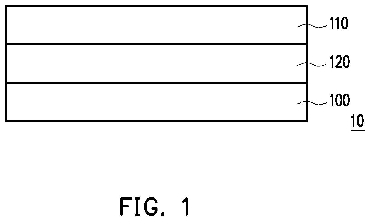
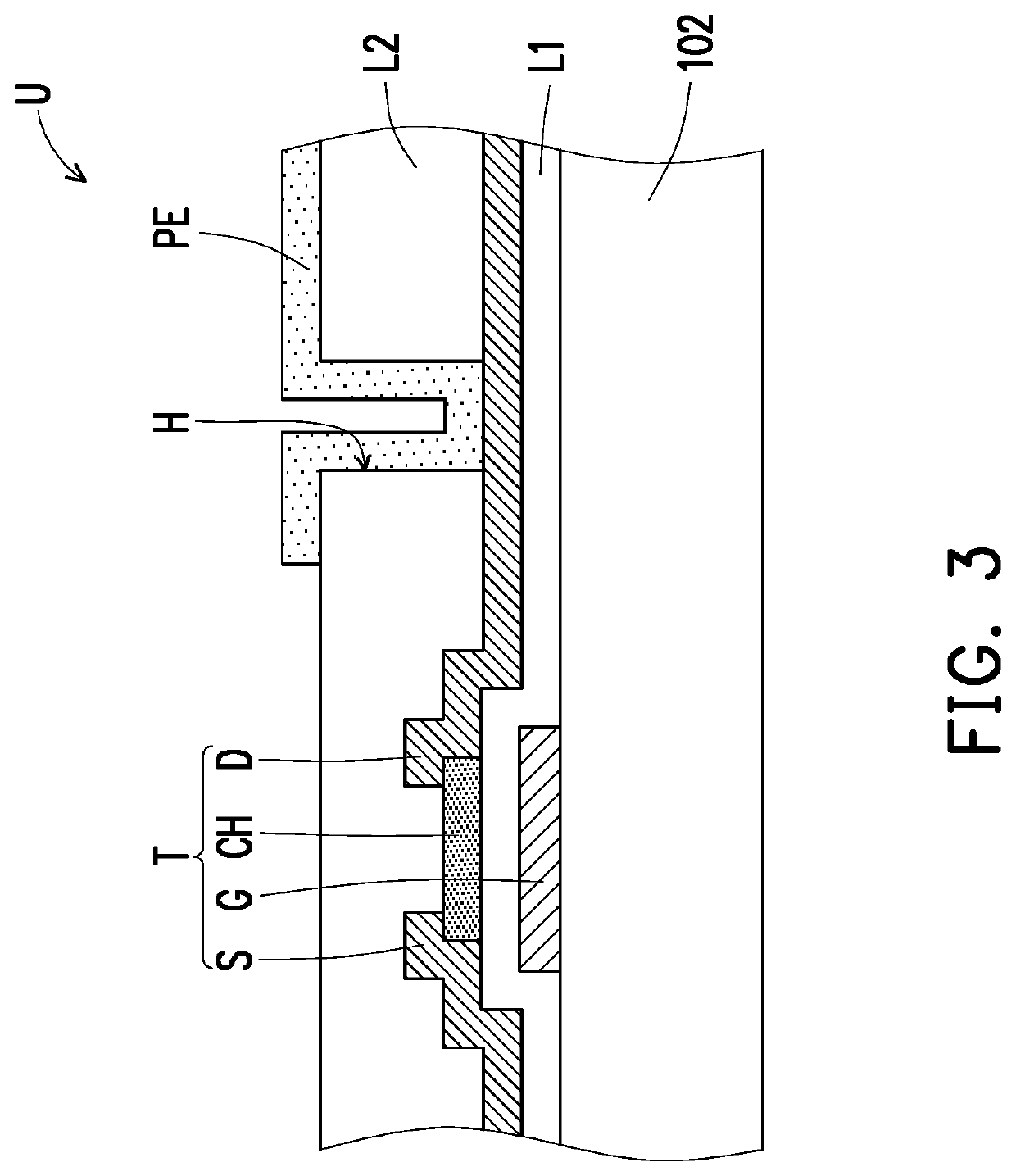
A display panel including a pixel array substrate, an opposite substrate, and a display media is provided. The pixel array substrate includes a substrate, a plurality of scan lines, a plurality of data lines, a plurality of pixel units, and a gate driving circuit. The gate driving circuit including a plurality of first signal lines, a plurality of second signal lines, a plurality of dummy signal lines, and a plurality of contact structures is disposed in a peripheral region of the substrate. Each of the second signal lines is electrically connected to one corresponding first signal line. Each of the dummy signal lines is electrically connected to one corresponding second signal line via one corresponding contact structure. Each of the first signal lines is electrically connected to the corresponding second signal line via one corresponding contact structure.

Description

CROSS-REFERENCE TO RELATED APPLICATION[0001]This is a divisional application of U.S. patent application Ser. No. 16 / 365,706, filed on Mar. 27, 2019, now allowed, which claims the priority benefit of Taiwan application serial no. 107114096, filed on Apr. 25, 2018. The entirety of each of the above-mentioned patent applications is hereby incorporated by reference herein and made a part of this specification.BACKGROUND OF THE INVENTIONField of the Invention[0002]The invention relates to a display panel, and more particularly, to a display panel having a gate driving circuit.Description of Related Art[0003]To achieve a display panel with narrow frame, a gate driver-on-array (GOA) technique has currently been developed. This technique includes forming a gate driving circuit structure driving a display panel in a peripheral region of the display panel to replace an external driver chip. As the demand for the resolution of the display panel continues to rise, the density of the signal line...

Claims


Application Information

Patent Timeline
Patent Type & Authority Patents(United States)
IPC IPC(8): G02F1/1362G02F1/1343G02F1/1345G02F1/1368
CPCG02F1/136286G02F1/1368G02F1/13439G02F1/13452G02F1/13454G02F1/136227G02F1/13629G02F1/136295G02F2201/123G09F9/00
Inventor KO, CHENG-HUNGCHEN, YI-FUCHANG, YU-SENCHEN, CHIA-HENGCHEN, HSIAO-CHUNLIN, YOU-YINGHSIEH, CHENG-AN
Owner AU OPTRONICS CORP
Learn More