Coaxial connector having inclined surface on tip end side of shell

a coaxial connector and tip end technology, applied in the field of electric connectors, can solve the problems of unnecessary reflection waves and difficulty in achieving the high frequency signal flowing through the contact in a high frequency band

Active Publication Date: 2022-09-08
JST MFG CO LTD
View PDF2 Cites 0 Cited by
  • Summary
  • Abstract
  • Description
  • Claims
  • Application Information

AI Technical Summary

Benefits of technology

[0010]In the present invention, the shape of a housing and the shape of a shell are designed so that the differenc

Problems solved by technology

Due to this, unnecessary reflected waves are generated in the high frequency signal flowing through the contact.
T

Method used


Image

  • Coaxial connector having inclined surface on tip end side of shell
  • Coaxial connector having inclined surface on tip end side of shell
  • Coaxial connector having inclined surface on tip end side of shell

Examples


Embodiment Construction

[0029]An embodiment of the present invention will be described below with reference to the drawings.

Configuration of Coaxial Connector

[0030]First, a configuration of a coaxial connector according to an embodiment of the present invention will be described.

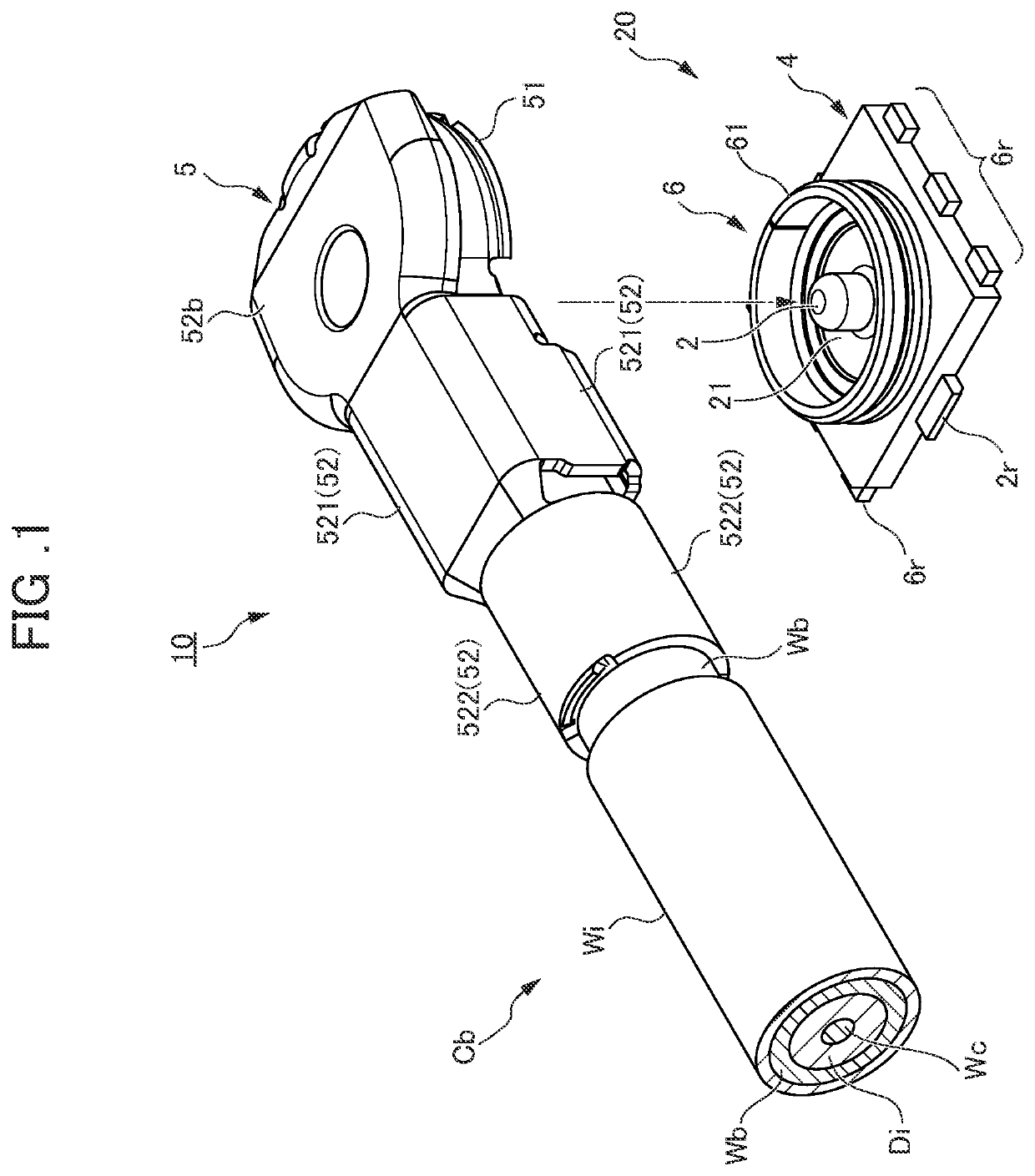
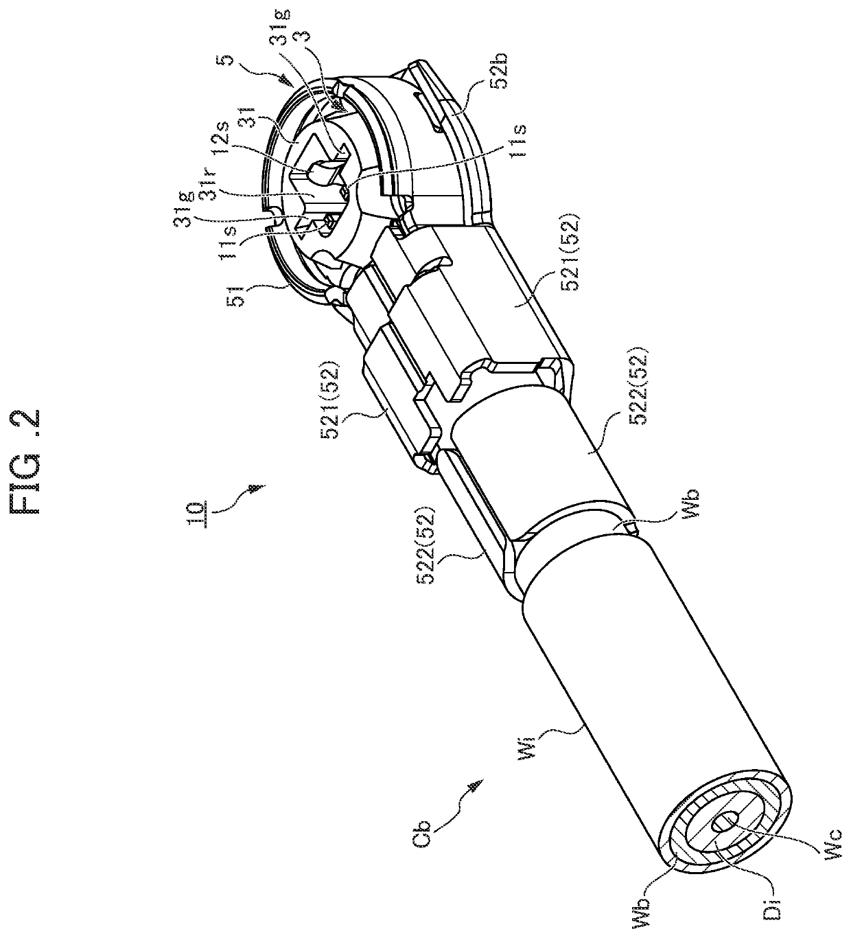
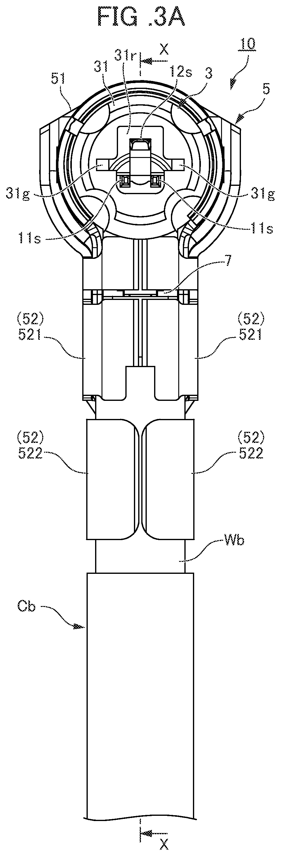
[0031]Overall Configuration With reference to FIGS. 1 to 6, a coaxial connector (hereinafter, also referred to as a plug) 10 according to an embodiment of the present invention is configured on an end of a coaxial cable Cb. The coaxial cable Cb includes a central conductor Wc, a dielectric Di surrounding the central conductor Wc, an external conductor Wb such as a braided wire that covers the dielectric Di, and an insulating sheath Wi that clads the external conductor Wb.

[0032]The coaxial plug 10 includes a contact 1 by a three-point contact, a housing 3 including first and second connection bases, and a conductive shell 5. Further, the housing 3 includes a block-shaped crimp housing 7. Further, the shell 5 includes a pair of first...


PUM


Abstract

The present invention provides a coaxial connector that realizes a high frequency signal flowing through a contact in a high frequency band. A coaxial connector includes a three-point contact, a housing including a first and a second connection base, and a shell including a cylindrical portion accommodating the first connection base and an extension portion covering one opening of the cylindrical portion with a bottom plate piece and accommodating the second connection base. The bottom plate piece includes an inclined surface having a higher side on the base end portion of the metal plate and a lower side on the tip end side of the metal plate. The distance between the metal plate of the contact and the bottom surface of the shell which are isolated by an insulating material of the housing is configured to become identical between the tip end side and the base end side of the contact.

Description

[0001]This application is based on and claims the benefit of priority from Japanese Patent Application No. 2021-035577, filed on 5 Mar. 2021, the content of which is incorporated herein by reference.BACKGROUND OF THE INVENTIONField of the Invention[0002]The present invention relates to an electrical connector. In particular, the present invention relates to a small-sized coaxial connector configured on an end of a coaxial cable and to a structure of the coaxial connector including a shell electrically connected to an external conductor of the coaxial cable on one end side and formed in a cylindrical shape on the other end side.Related Art[0003]The coaxial connector fixed to the terminal of the coaxial cable is connected to a receptacle mounted on a printed circuit board, and thus a high frequency signal can be transmitted from the coaxial cable to the printed circuit board. Alternatively, the high frequency signal can be transmitted from the printed circuit board to the coaxial cabl...

Claims


Application Information

Patent Timeline
IPC IPC(8): H01R24/40
CPCH01R24/40H01R2103/00H01R24/50H01R24/44H01R13/46H01R13/02H01R9/0518
Inventor KOGA, SHINICHIOTSU, AKIHIKO
Owner JST MFG CO LTD
Why Eureka
Try Eureka