Electro optical phase modulator with frequency state feedback function

An electro-optical phase modulation and feedback signal technology, applied in instruments, optics, nonlinear optics, etc., to avoid impedance mismatch problems and improve modulation efficiency

Active Publication Date: 2014-04-16
SHANGHAI MICRO ELECTRONICS EQUIP (GRP) CO LTD
View PDF3 Cites 0 Cited by
  • Summary
  • Abstract
  • Description
  • Claims
  • Application Information

AI Technical Summary

Problems solved by technology

[0006] Aiming at the problem of the resonance frequency drift of the electro-optic phase modulation crystal in the application process of the existing electro-optic phase modulation technology, the present invention proposes a design scheme of a phase modulator. The phase modulator can feed back a signal according to the frequency of the input driving signal to Indicate the relationship between the frequency of the current driving signal and the resonant frequency of the phase modulator, so as to facilitate the modulation signal source to track the resonant frequency of the phase modulator, thereby reducing the impact caused by impedance mismatch

Method used


Image

  • Electro optical phase modulator with frequency state feedback function
  • Electro optical phase modulator with frequency state feedback function
  • Electro optical phase modulator with frequency state feedback function

Examples


no. 1 example

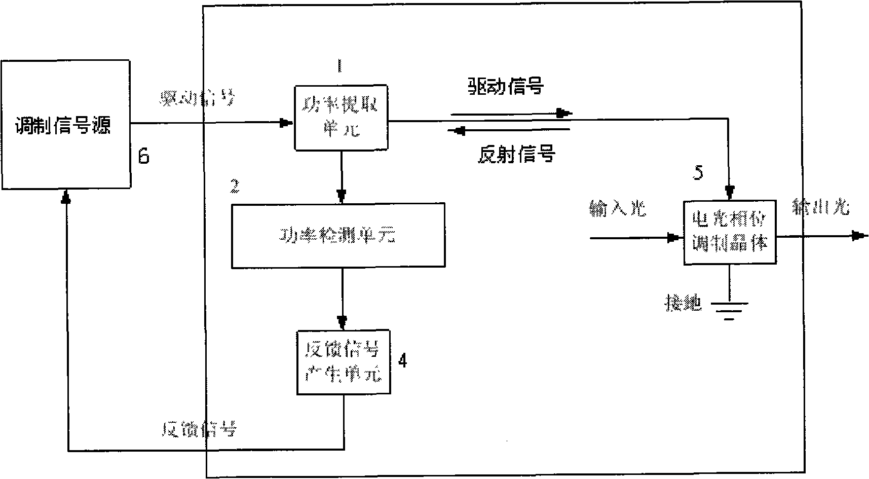
[0036]The phase modulator according to the first embodiment of the present invention includes:

[0037] The power extraction unit 1 includes a directional coupler, which can be a directional coupler in the form of a microstrip circuit structure or other structures, and is used to extract the power of the driving signal and the power of the interference signal between the driving signal and the reflected signal.

[0038] The driving power detection unit 2a includes an attenuation circuit with an appropriate multiple and a logarithmic detection chip. It is used to convert the power value of the driving signal extracted by the power extraction unit into a corresponding voltage value. The attenuator may be a π-type attenuator or a T-type attenuator composed of three resistors. The logarithmic detection chip can be selected from an existing IC chip, such as AD8313. One of its specific implementation methods can refer to Figure 5 .

[0039] The coherent power detection unit 2b ...

no. 2 example

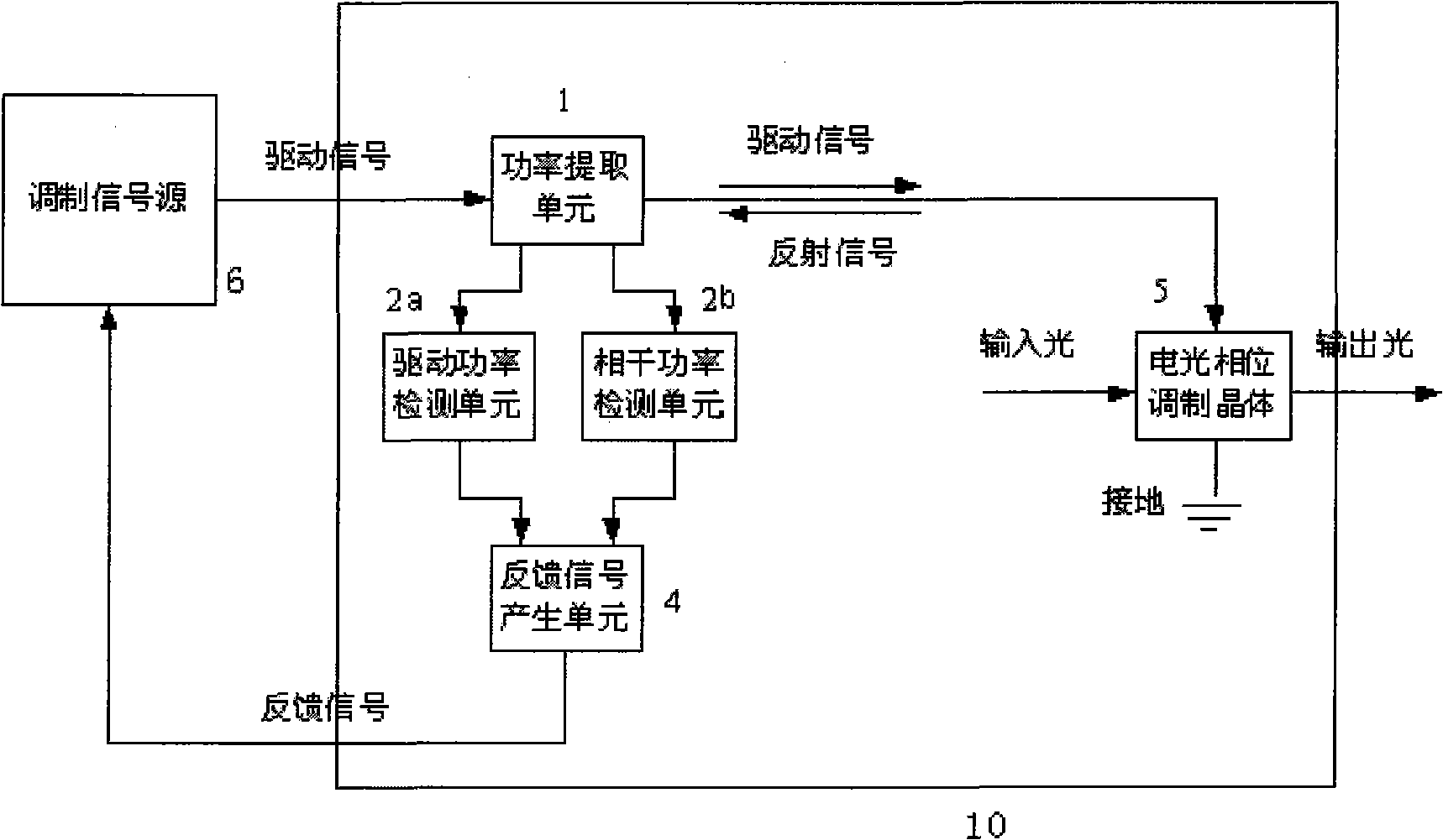
[0044] A phase modulator according to a second embodiment of the present invention includes:

[0045] The power extraction unit 1 includes a directional coupler, which can be a directional coupler in the form of a microstrip circuit structure or other structures, and is used to extract the power of the driving signal and the power of the interference signal between the driving signal and the reflected signal.

[0046] The driving power detection unit 2a includes an attenuation circuit with an appropriate multiple and a logarithmic detection chip. It is used to convert the power value of the driving signal extracted by the power extraction unit into a corresponding voltage value. The attenuator may be a π-type attenuator or a T-type attenuator composed of three resistors. The logarithmic detection chip can be selected from an existing IC chip, such as AD8313. One of its specific implementation methods can refer to Figure 5 .

[0047] The coherent power detection unit 2b in...


PUM


Abstract

The invention discloses an electro optical phase modulator with a frequency state feedback function. The modulator comprises a power extraction unit, a power detection unit, a feedback signal generation unit and an electro optical phase modulation crystal, wherein the electro optical phase modulation crystal modulates the phase of an input light beam; the power extraction unit extracts a power signal and a drive signal in the drive signal output from a modulation signal source and the power signal of an interference signal of a reflection signal obtained by reflecting the drive signal through the electro optical phase modulation crystal; the power detection unit converts the power signal into an electric signal; the feedback signal generation unit generates feedback information according to the electric signal and feeds the feedback information back to the modulation signal source; and the modulation signal source regulates the drive signal according to a feedback signal so as to keep the frequency value of the drive signal close to the resonance frequency of the phase modulator.

Description

technical field [0001] The invention relates to an electro-optical phase modulator, in particular to an electro-optical phase modulator used in the field of photoelectric detection. Background technique [0002] In the field of weak photoelectric detection, due to the inevitable existence of a certain number of multi-order reflection ghost beams during the transmission of the optical system, the ghost beam generated after multiple reflections has the phase and frequency of the main beam at the same point. The phase and frequency are exactly the same, so that interference occurs between the ghost beam and the main beam, resulting in a deviation between the detected optical signal and the ideal optical signal, resulting in corresponding measurement errors in the actual measurement results. In order to reduce or even avoid the interference of ghost images on the main beam, phase modulation technology is used in many weak photoelectric detection systems to artificially destroy t...

Claims


Application Information

Patent Timeline
Patent Type & Authority Patents(China)
IPC IPC(8): G02F1/03
Inventor 陈振飞唐文力王海江韦学志
Owner SHANGHAI MICRO ELECTRONICS EQUIP (GRP) CO LTD
Why Eureka
Try Eureka