Dielectric resonator antenna module and communication terminal
A technology of dielectric resonator and antenna module, applied in the direction of resonator, antenna grounding switch structure connection, waveguide type device, etc. The effect of preventing impedance mismatch, expanding antenna bandwidth, and improving antenna reliability
- Summary
- Abstract
- Description
- Claims
- Application Information
AI Technical Summary
Problems solved by technology
Method used
Image
Examples
Embodiment 1
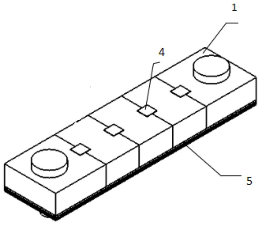
[0060] Such as image 3 As shown, a dielectric resonator antenna module includes a dielectric resonator 4, a plastic clamp 1 and a PCB board 5;
[0061] Wherein, the difference between the dielectric constant of the plastic fixture 1 and the dielectric constant of the PCB board 5 is within the range of ±0.5, and the plastic fixture 1 can be made of ABS plastic with a dielectric constant of 2.5;
[0062] The plastic fixture 1 clamps the dielectric resonator 4, and the dielectric resonator 4 runs through the plastic fixture 1;
[0063] The plastic clamp 1 is fixed on one side of the PCB board 5;
[0064] The one side of the PCB board 5 is completely attached to one side of the dielectric resonator 4;
[0065] In an alternative embodiment, such as Figure 4 As shown, the two ends of the plastic clamp 1 have through holes, and the two ends of the PCB board 5 have second through holes, and the second through holes match the shape of the through holes and correspond to the positi...
Embodiment 2
[0069] On the basis of the first embodiment, this embodiment further defines the structure of the plastic clamp 1 for clamping the dielectric resonator 4;
[0070] Such as Figure 5 As shown, the plastic clamp 1 includes a plurality of flaps 6 connected in sequence;
[0071] The side of the flap 6 facing the flap adjacent to it includes a groove 7;
[0072] The groove 7 adjacent to the clip 6 cooperates to form the clamping portion;
[0073] The clamping part clamps the dielectric resonator 4, and the dielectric resonator 4 passes through the clamping part;
[0074] Preferably, the shape of the clamping part is adapted to the shape of the dielectric resonator. By setting the shape of the clamping part and the dielectric resonator to fit, the plastic clamp can produce a better clamping of the dielectric resonator Strength, which will not cause pressure damage to the dielectric resonator and can keep the position of the dielectric resonator from shifting when the module moves...
Embodiment 3
[0078] A communication terminal applied to 5G, including the dielectric resonator antenna module described in Embodiment 1 or Embodiment 2. 5G communication usually uses millimeter waves, but the path loss of millimeter waves in the air is relatively large, so in the communication terminal The dielectric resonator can be in the form of an array antenna to compensate for path loss and increase antenna gain. This embodiment further defines the dielectric resonator 4;
[0079] The dielectric resonator 4 includes a preset number of dielectric units 12 arranged in a preset order;
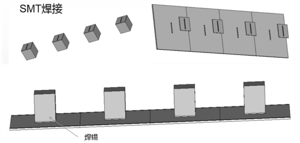
[0080] Specifically, such as Figure 13 As shown, the dielectric resonator 4 includes four linearly arranged dielectric units 12, the shape of the dielectric unit 12 is rectangular, the dielectric constant is 21, and the dielectric loss is 0.0001;
[0081] The plastic clamp 1 includes the clamping parts corresponding to the medium units 12 one by one;
[0082] The clamping parts clamp the medium units ...
PUM
 Abstract
Description
Claims
Application Information
 - R&D
- Intellectual Property
- Life Sciences
- Materials
- Tech Scout
- Unparalleled Data Quality
- Higher Quality Content
- 60% Fewer Hallucinations
Browse by: Latest US Patents, China's latest patents, Technical Efficacy Thesaurus, Application Domain, Technology Topic, Popular Technical Reports.
© 2025 PatSnap. All rights reserved.Legal|Privacy policy|Modern Slavery Act Transparency Statement|Sitemap|About US| Contact US: help@patsnap.com


