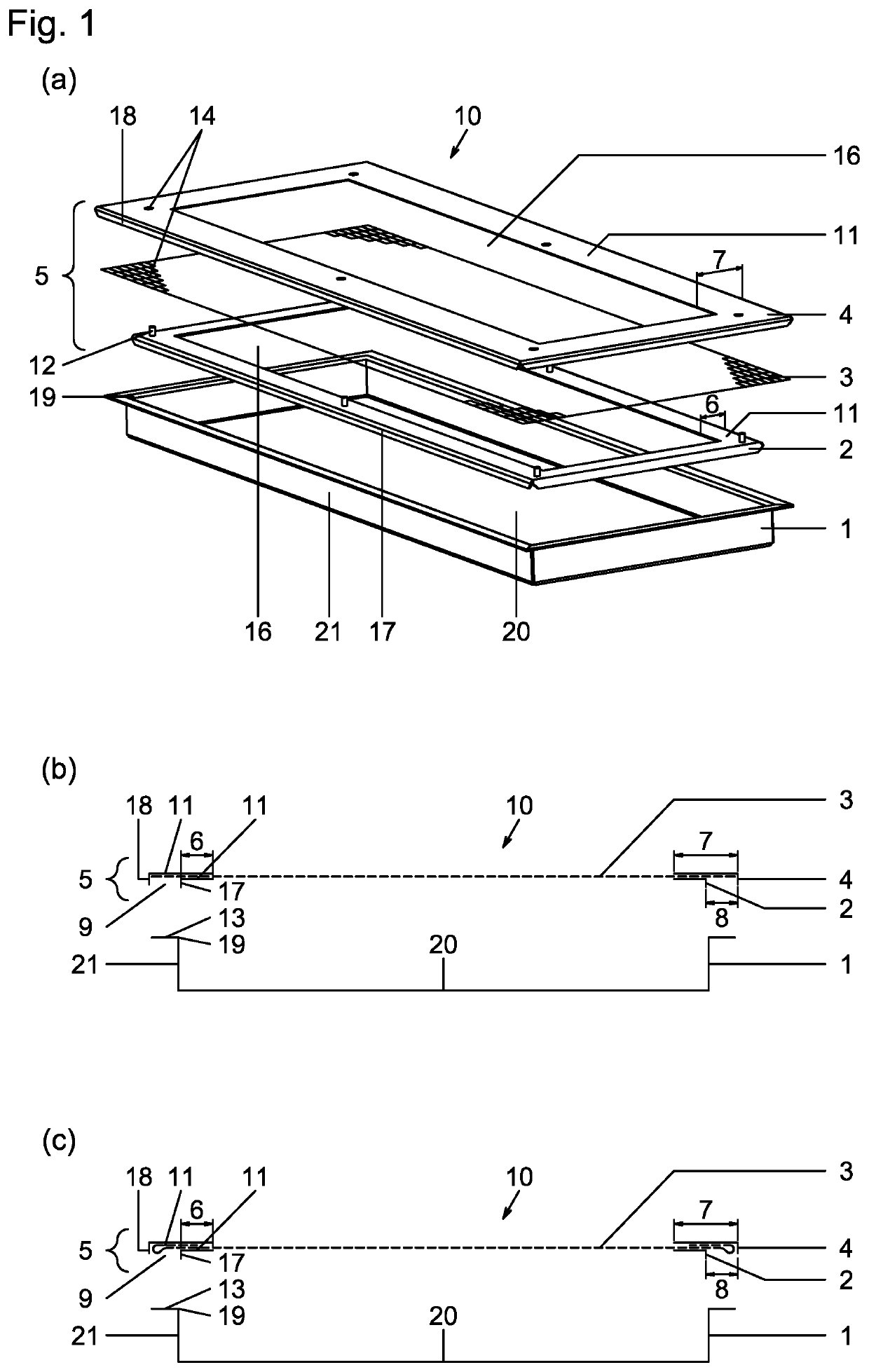
Drying container

a container and container technology, applied in the direction of drying solid materials, drying, lighting and heating equipment, etc., can solve the problems of contaminating the material to be dried, the risk of liquid or solid spillage of the material to the surrounding environment, and the difficulty in containing the dried product, which often forms fine powders or dusts,

Active Publication Date: 2022-07-05
BACHEM HOLDING
View PDF43 Cites 8 Cited by
  • Summary
  • Abstract
  • Description
  • Claims
  • Application Information

AI Technical Summary

Benefits of technology

[0047]Typical drying containers have a width in the range of 20 to 40 cm, a length in the range of from 30 to 80 cm and a height of from 3 to 15 cm. It should be noted, however, that one advantage of the present invention is that the size and shape of the drying container is very flexible and can be adapted to the specific needs encountered, e.g. to allow for optimal use of space in a given drying chamber.
[0048]It is a further aspect of the invention to provide a method for drying of materials. The method comprises the following steps:
[0049]a) introducing the material to be dried into a container body,
[0050]b) closing said container body by means of one of the described lid assemblies, and
[0051]c) exposing the closed drying container to conditions suitable to effect drying,
[0052]wherein steps a) and b) can be carried out in any order.

Problems solved by technology

The use of such open containers is however disadvantageous in that it bears the double risk of contaminating the material to be dried and of causing liquid or solid spills of said material to the surroundings.
The containment of the dried product, which often forms fine powders or dust, is particularly challenging.
During lyophilization, evaporation of the solvent at reduced pressure and subsequent ventilation of the drying chamber may give rise to turbulences and cause spills of fine solid particles of the dried product.
Each of the above lyophilization containers is designed for single use and thus is resource intensive.
Moreover, cutting the container open to recover the dry material bears the risk of introducing debris into the dried product.
As the trays are made from synthetic resin, leachables and extractables may be an issue, depending on the solvents present in the material to be dried.
Moreover, such elastic sealing elements are prone to wear and difficult to clean.
The membrane area is small compared to the surface area of the tray, which hinders evaporation of solvent and results in high vapor pressure inside the container.
This is undesirable because it may cause inhomogeneity of the resulting lyophilizate as well as leakage due to lifting of the lid, and brings about the need for slow lyophilization cycles to avoid product melt-back.

Method used


Image

  • Drying container
  • Drying container
  • Drying container

Examples


example 1

[0144]To investigate the need for an elastomeric seal, 20 drying containers as depicted in FIG. 14 were assembled with an additional silicone flat seal inserted between the sheet and frame F2 of the lid. The container body, lower frame F1, upper frame F2 and spring clamps were made from stainless steel, a PTFE (polytetrafluoroethylene) membrane with 1-2 μm pore size served as the sheet. The port incorporated into F1 was closed by a screw cap. The drying containers were placed onto the shelfs of a lyophilization chamber.

[0145]Each drying container was filled with about 5 l of an aqueous paracetamol solution (10 g / l) using a peristaltic pump, whose outlet tube was connected to the drying container's port. After removal of the tube, a temperature sensor was inserted into the port, the lyophilization chamber was closed, and the lyophilization program started.

[0146]After the end of the lyophilization program and venting of the lyophilization chamber, swab tests were taken on the surface ...

example 2

[0149]10 drying containers as depicted in FIG. 14 were assembled and placed onto the shelfs of a lyophilization chamber. The container body, lower frame F1, upper frame F2 and spring clamps were made from stainless steel, a PET (Polyethylenterephthalate) membrane with 7 μm pore size served as the sheet, and was folded back to form a double layer within the lid assembly's circumferential channel (cf. FIG. 1c). The port incorporated into F1 was closed by a screw cap.

[0150]Each drying container was filled with about 5 l of an aqueous paracetamol solution (10 g / l) using a peristaltic pump, whose outlet tube was connected to the drying container's port. After removal of the tube, a temperature sensor was inserted into the port, the lyophilization chamber was closed, and the lyophilization program started.

[0151]After the end of the lyophilization program and venting of the lyophilization chamber, swab tests were taken on the surface of the drying containers and inside the lyophilization c...


PUM


Abstract

The invention relates to containers for the drying, especially the freeze-drying, of material. In particular, the invention relates to a lid of a drying container, said lid enabling to close the container body of the drying container so as to avoid i) contamination of the material to be dried inside the container and ii) spills of airborne solid particles of said material from the container to the environment. The lid comprises a lower and an upper frame with a vapor permeable sheet positioned in between. The invention further provides methods for the drying, especially the freeze-drying, of material.

Description

[0001]The present invention generally relates to containers for the drying of material. In particular, the invention relates to a lid of a drying container, said lid enabling to close the container body of the drying container so as to avoid i) contamination of the material to be dried inside the container and ii) solid and optionally liquid spills of said material from the container to the environment. The invention further provides drying containers comprising a container body and said lid, and methods for the drying of material. The containers and methods of the present invention are in particular suitable for freeze-drying of bulk material, such as biological material or pharmaceutical products.[0002]Drying is a common step in many industrial processes, e.g. in the food, chemical, and pharmaceutical industry. The drying of bulk material such as slurries, suspensions, or liquid solutions is commonly carried out in open containers, e.g. in flat open trays. These are placed in a dr...

Claims


Application Information

Patent Timeline
Patent Type & Authority Patents(United States)
IPC IPC(8): B65D51/24B65D45/16
CPCB65D51/241B65D45/16F26B5/06
Inventor MUELLER, ANDREASERDIN, CHRISTOPH
Owner BACHEM HOLDING
Why Eureka
Try Eureka