Turning tool and method for metal cutting

a turning tool and metal cutting technology, applied in the field of metal cutting, can solve the problems of poor chip breaking, poor chip evacuation, and less cost-efficient use of two separate turning tools, and achieve the effects of less cost-effective and time-consuming

Active Publication Date: 2022-07-26
SANDVIK INTELLECTUAL PROPERTY AB
View PDF24 Cites 2 Cited by
  • Summary
  • Abstract
  • Description
  • Claims
  • Application Information

AI Technical Summary

Benefits of technology

[0006]When using the known turning tool for longitudinal turning into the hole, and especially at cutting depths that are equal to or less than the nose radius or corner radius of the turning insert, the chip breaking is poor, which results in, e.g. poor chip evacuation. Thus there is a need to reduce the wear of the turning insert of the known turning tool. Longitudinal turning of a hole may in many cases preferably be made in two or more passes, such as a first pass for roughing followed by a second finishing pass. therefore, the cutting portion of the tool should preferably be different when roughing compared to finishing. In such cases, using two separate turning tools is less cost-efficient and more time-consuming, as well as presenting other draw-backs.
[0007]An object of the present invention is to provide a turning tool which is suitable for internal longitudinal turning, especially for generating an inner surface having a constant diameter, where higher feed rate can be used when feeding into a hole of a metal work piece. A further object is to improve chip evacuation from a hole of metal work piece.

Problems solved by technology

When using the known turning tool for longitudinal turning into the hole, and especially at cutting depths that are equal to or less than the nose radius or corner radius of the turning insert, the chip breaking is poor, which results in, e.g. poor chip evacuation.
In such cases, using two separate turning tools is less cost-efficient and more time-consuming, as well as presenting other draw-backs.

Method used


Image

  • Turning tool and method for metal cutting
  • Turning tool and method for metal cutting
  • Turning tool and method for metal cutting

Examples


first embodiment

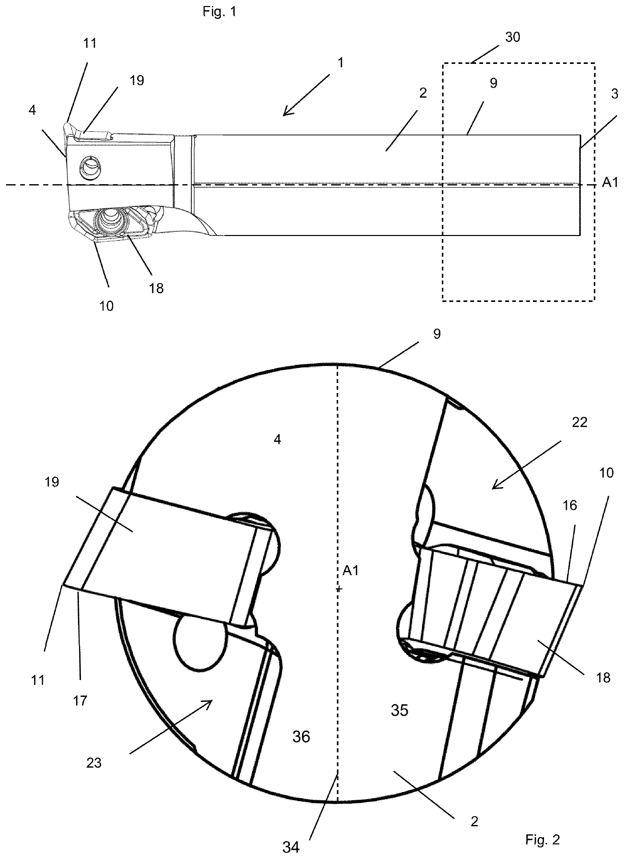
[0178]Reference is made to FIGS. 1-8, which show a turning tool 1 according to a

[0179]The turning tool 1 comprises a rear end 3, an opposite forward end 4 and a longitudinal center axis A1 extending therebetween.

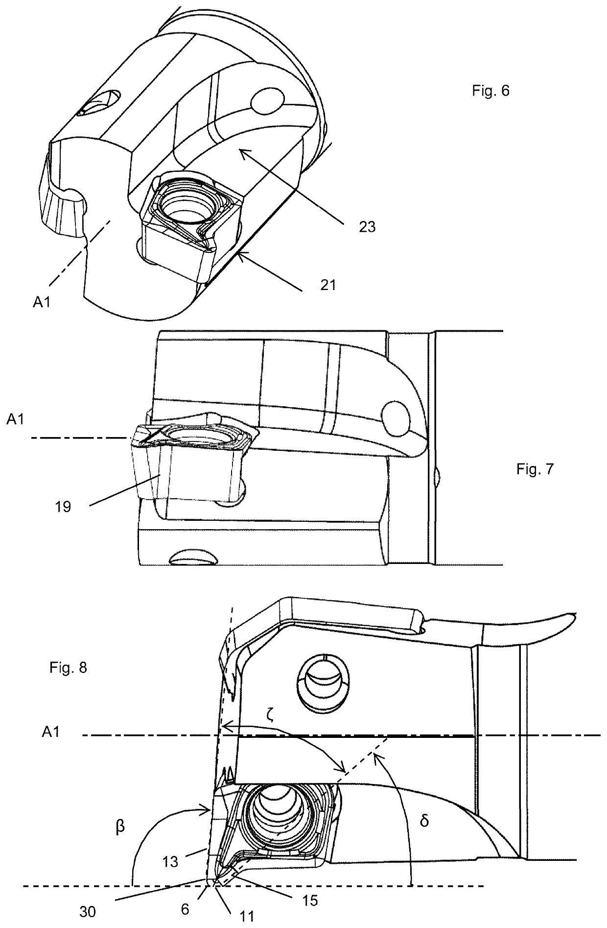
[0180]The rear end 3 is clamped to a machine interface 30 of a machine tool, such as a numerical control lathe (not shown). The turning tool 1 comprises a tool body 2, a first turning insert 18 and a second turning insert 19. The tool body 2 comprises an external peripheral surface 9 which comprises a portion which is circular or substantially circular in cross sections perpendicular to the longitudinal center axis A1. The tool body 2 comprises a first insert seat 20 and an opposite second insert seat 21, a first chip pocket 22, adjacent to the first insert seat 20, and an opposite second chip pocket 23, adjacent to the second insert seat 21,

[0181]The first and second insert seats 20, 21 are spaced apart. The first and second chip pockets 22, 23 are spaced apart. The first a...

second embodiment

[0183]All the above is valid also for the turning tool seen in FIGS. 20-23.

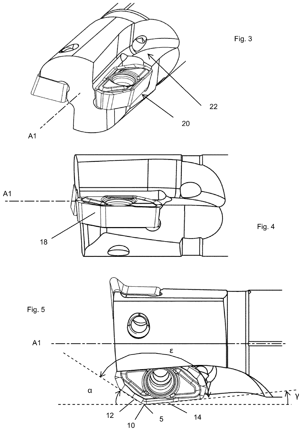
[0184]As seen in e.g. FIGS. 9-11, the first turning insert 18 which is part of the turning tool according to the first embodiment comprises a first top surface 26, comprising the first rake face 16, and an opposite first bottom surface 28, a first nose cutting edge 5, a first forward cutting edge 12 and a first rearward cutting edge 14.

[0185]The first nose cutting edge 5 comprising a first radially distal point 10, when the first turning insert 18 is mounted in the first insert seat 20. The first nose cutting edge 5 separates and connects the first forward cutting edge 12 and the first rearward cutting edge 14, where said edges 5, 12, 14 are formed at an intersection between the first top surface 26 and a first side surface, where said first side surface connects the top and bottom surfaces 26, 28.

[0186]As can be seen in FIG. 5, the first forward cutting edge 12 forms an acute first entering angle α in longi...


PUM

PropertyMeasurementUnit
entering angleaaaaaaaaaa
clearance angleaaaaaaaaaa
entering angleaaaaaaaaaa

Abstract

A turning tool for internal turning of a metal work piece having a rear end, an opposite forward end and a longitudinal center axis extending therebetween. The first nose cutting edge includes a first radially distal point having an associated first rake face and separates and connects a first forward cutting edge and a first rearward cutting edge. A second nose cutting edge of the turning tool includes a second radially distal point having an associated second rake face and separates and connects a second forward cutting edge and a second rearward cutting edge. The second radially distal point is positioned ahead of the first radially distal point. The first forward cutting edge forms an acute first entering angle, the second forward cutting edge forms an obtuse second back clearance angle, and the second rearward cutting edge forms an acute second entering angle.

Description

RELATED APPLICATION DATA[0001]This application is a § 371 National Stage Application of PCT International Application No. PCT / EP2018 / 057164 filed Mar. 21, 2018 claiming priority to EP 17191355.1 filed Sep. 15, 2017.TECHNICAL FIELD OF THE INVENTION[0002]The present invention belongs to the technical field of metal cutting.[0003]More specifically the present invention belongs to the field of turning tools for internal turning, for metal cutting in machines such as computer numerical control, i.e. CNC, machines.BACKGROUND OF THE INVENTION AND PRIOR ART[0004]The present invention refers to a turning tool for internal turning of a metal work piece, comprising a rear end, an opposite forward end and a longitudinal center axis extending therebetween, a first nose cutting edge comprising a first radially distal point having an associated first rake face, the first nose cutting edge separating and connecting a first forward cutting edge and a first rearward cutting edge.[0005]Such a turning ...

Claims


Application Information

Patent Timeline
Patent Type & Authority Patents(United States)
IPC IPC(8): B23B27/14B23B1/00B23B29/24
CPCB23B27/145B23B1/00B23B29/24B23B2200/0423B23B27/005B23B27/007B23B2200/28B23B2210/02B23B2220/445
Inventor JOHANSSON, ADAMLOF, RONNIE
Owner SANDVIK INTELLECTUAL PROPERTY AB
Why Eureka
Try Eureka