Methods for the correction of axis motions

a technology of axis motion and correction method, applied in the field of methods for the correction of axis motion, can solve the problems of limited measurement compensation, slide will show a vertical straightness deviation and pitch error motion, and geometric motion errors

Active Publication Date: 2022-08-02
AGIE CHARMILLES
View PDF7 Cites 0 Cited by
  • Summary
  • Abstract
  • Description
  • Claims
  • Application Information

AI Technical Summary

Benefits of technology

[0018]It is an aspect of this invention to overcome the disadvantages of the known methods and to provide an improved, quick, precise, efficient, reliable and economically affordable method for the mechanical correction of high accuracy mechanisms, such as to provide an improved accuracy of axis motion. The correction is established by measuring the geometrical deviations contributing to the axis accuracy such as the mounting surfaces of guideways, in combination with the calculation of the deformations due to gravity, taking into account the position dependency of these deviations. The measured and the calculated deviations are used to determine the mounting surface correction profile. This profile serves as input value to mechanically modify the axis geometry by means of laser machining, to compensate the cumulated deviations.
[0020]The amounts of material determined by the mounting surface correction profile can be precisely and selectively removed by a suitable machining process, e.g. laser machining. The mounting surface correction profile specifies the amounts of material to be removed from the mounting surface in function of the position. In this way the mounting surface correction profile is quickly, precisely and permanently imparted to a mounting surface of the axis guide component or to a mounting surface of the machine frame component, such as to achieve an optimal axis motion accuracy of the assembled positioning machine.
[0024]According to an aspect of the present invention, the geometric error of the mounting surface of the individual machine frame component is firstly determined by measurement, and then said measurement is corrected in consideration of the deformation experienced by the individual machine frame component in the measuring configuration. In this way, the measured deviation at the mounting surface of the individual machine frame component is free from deviations that are due to the particular measuring setup.

Problems solved by technology

Geometric motion errors are errors due to imperfect geometry and dimensions of machine components as well as their configuration in the machine's structural loop, axis misalignment and errors in the machine's measuring system.
For instance, if straight guideways bend due to the weight of the moving slide, the slide will show a vertical straightness deviation and a pitch error motion.
Software compensation based on measurements is limited by a number of aspects including the uncertainty of the measurement and the repeatability of the mechanical system.
Applying numerical compensation to machines with noticeable hysteresis may also have negative effects.
However this motion in combination with a hysteresis of the Z-axis may harm the surface finish quality.
Additionally, for the correction of rotational errors corresponding rotary axes would be required, which are not available in the case for three axis machines.
To date the application of at least partially automated hardware correction techniques is limited by the difficulty to manufacture the intended corrective shape with the available methods, e.g. a grinding process.
These methods are unable to create a defined corrugated geometry having micrometer amplitude on a surface.
Therefore manual scraping as additional iterative machining step is sometimes applied, but manual scraping has deficiencies which lie in the staff cost, the long duration of the process and the default of skilled personnel for this work.
In summary, today there is no viable solution for a mechanical correction of geometric motion errors and mechanical correction of deformation of the structural loop due to gravity during displacement of mechanical components, that is the mechanical correction of systematic deviations encountered in a high precision positioning machine.
The at least partial mechanical correction of systematic errors in high precision positioning machines is highly desirable, but known methods have severe technical limitations and lack in their industrial applicability due to the cost and technical reasons.

Method used


Image

  • Methods for the correction of axis motions
  • Methods for the correction of axis motions
  • Methods for the correction of axis motions

Examples


Embodiment Construction

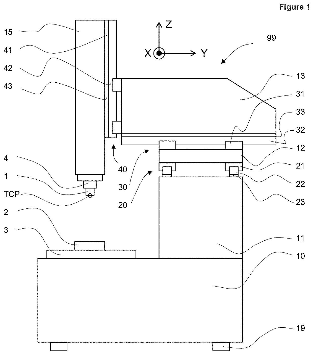
[0062]For clarity a number of terms used in the present invention are first explained.

[0063]According to the present invention the term “mounting surface” is used to define the supporting surfaces of the machine frame component where the axis guideway is mounted, the supporting surfaces of the guideway, in particular the bottom or side surface of the rail, and the surfaces of an intermediate component. The intermediate component is a mechanical component mounted between the rail of the guideway and the mounting surface of the machine frame component. This intermediate component is a shimming foil. The size of the mounting surface corresponds essentially to the bottom surface of the guideway rail. Mounting surfaces are relevant for the straightness of an axis motion.

[0064]According to the present invention, the guideways, the intermediate component (shim) and the mounting surface of the machine fame component which is adjacent to a guideway are defined as “axis guide component”. Axis...


PUM

PropertyMeasurementUnit
volumeaaaaaaaaaa
thicknessaaaaaaaaaa
depthaaaaaaaaaa

Abstract

A method for the mechanical correction of geometric motion errors of a positioning machine having at least two machine frame components and at least one axis movement assembly for the relative movement of the machine frame components, the at least one axis movement assembly comprising a plurality of axis guide components, each axis guide component and each machine frame component having a mounting surface. A mounting surface correction profile is determined for the considered axis, whereas the mounting surface correction profile describes the correction amounts in function of the position for the mechanical correction of the considered axis. The determined mounting surface correction profile is imparted to the mounting surface of the axis guide component or to the mounting surface of the machine frame component of the considered axis by machining.

Description

CROSS-REFERENCE TO RELATED APPLICATIONS[0001]This application claims the benefit and priority of European Patent Application No. 18 212 589.8 filed Dec. 14, 2018 and is incorporated by reference herein in its entirety.DESCRIPTION[0002]The present invention relates to a mechanical correction method to improve the geometric accuracy of axis movements of positioning machines such as machine tools, measuring machines, manipulators, and robots.BACKGROUND OF THE INVENTION[0003]Machine tools, coordinate measuring machines, etc. are high precision positioning machines, build-up of a structural loop which is constituted by a base and a number of linear and / or rotary axes connecting a work piece and a tool side. The structural loop is defined as an assembly of mechanical components, which maintain a relative position between specified objects. In a machine tool the structural loop includes the machine frame, guideways, bearings, drives, transmission and the tool and work-holding fixtures. The...

Claims


Application Information

Patent Timeline
Patent Type & Authority Patents(United States)
IPC IPC(8): B25J9/16
CPCB25J9/1692B23K26/08B23K26/00B23Q15/14G05B19/404G05B2219/49177G01B5/0016G01B5/0009B23Q11/001
Inventor WEIKERT, SASCHA
Owner AGIE CHARMILLES
Why Eureka
Try Eureka