Supercharge Your Innovation With Domain-Expert AI Agents!

Boundary layer ingestion fan system

a technology of ingestion fan and boundary layer, which is applied in the direction of air-flow influencers, machines/engines, transportation and packaging, etc., can solve the problem that little published work to date has investigated the required aerodynamic design of turbomachines

Active Publication Date: 2022-08-16
ROLLS ROYCE PLC
View PDF36 Cites 0 Cited by
  • Summary
  • Abstract
  • Description
  • Claims
  • Application Information

AI Technical Summary

Benefits of technology

The patent describes a boundary layer ingestion fan system for use in an aircraft. This system includes a nacelle with a duct and a fan located inside. The fan has blades that rotate around a rotational axis and have a different span position for each blade. The blade has a thickness and an angle, and there is a pitch between the blades at each position. The system also has sufficient distortion tolerance to withstand the installation process. The technical effect of this system is increased efficiency and improved performance of the aircraft.

Problems solved by technology

The limiting case of ηp=1 occurs when the jet velocity matches the inlet velocity; however this is unachievable with a finite propulsor size that produces thrust.
Whilst significant simulation and prediction has been performed in multiple research programmes to quantify the theoretical benefit of BLI, little published work to date has investigated the required aerodynamic design of a turbomachine that may be used in a fuselage BLI installation on a conventional tube-and-wing aircraft.

Method used


Image

  • Boundary layer ingestion fan system
  • Boundary layer ingestion fan system
  • Boundary layer ingestion fan system

Examples


Embodiment Construction

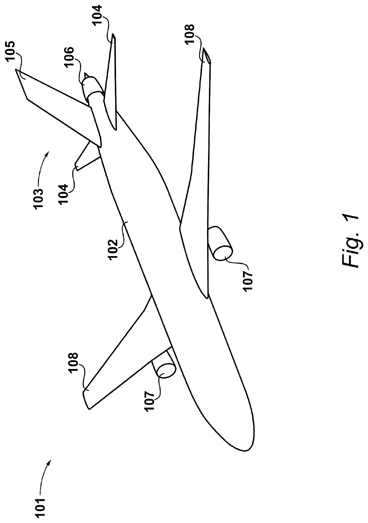
[0045]A tube-and-wing-configuration aircraft 101 according to an embodiment is shown in FIG. 1.

[0046]In the present example, the aircraft 101 comprises a fuselage 102 with a conventional empennage 103 mounted thereto. Thus, both the tailplane 104 and vertical stabiliser 105 are mounted to the fuselage 102. The aircraft 101 further comprises a BLI fan system 106 mounted aft of the fuselage 103 and the empennage 103. In the present example the aircraft 101 is a twinjet and thus comprises two turbofan engines 107 mounted under a respective wing 108. It will be appreciated however that a greater number of engines may be provided depending upon the aircraft configuration. Further, a different engine configuration such as open rotor may be used.

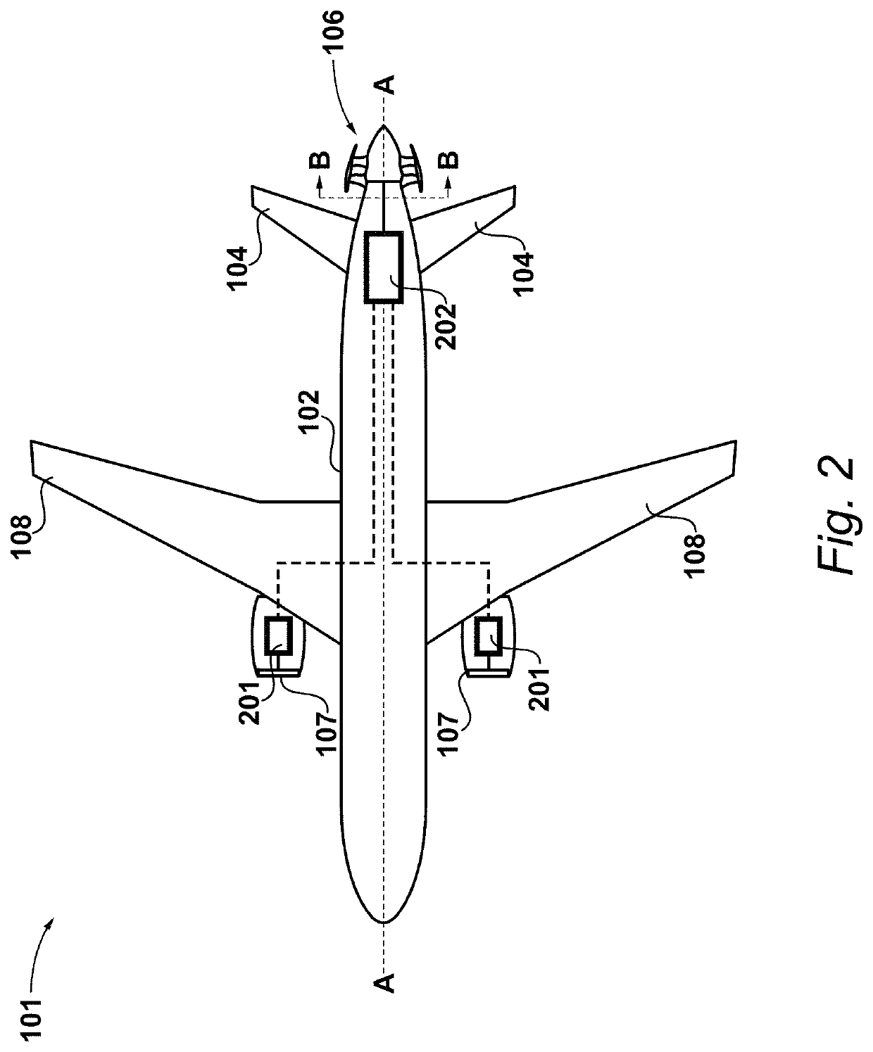
[0047]A schematic of the propulsion system of the aircraft 101 is shown in FIG. 2.

[0048]In the present example, the BLI fan system 106 comprises a fan that is electrically-driven. The turbofan engines 107 therefore each comprise an electric machine...


PUM


Abstract

A boundary layer ingestion fan system for location aft of the fuselage of an aircraft is shown. It comprises a nacelle defining a duct, and a fan located within the duct. The fan comprises a hub arranged to rotate around a rotational axis (A-A) and a plurality of blades attached to the hub. A blade blockage, which is the ratio of the blade thickness to the product of the circumferential pitch and the cosine of a blade inlet angle (t / s·cosβ1), is 0.25 or greater at the 0 percent span position.

Description

CROSS-REFERENCE TO RELATED APPLICATIONS[0001]This application is based upon and claims the benefit of priority from British Patent Application No. GB 1818683.3, filed on 16 Nov. 2018, the entire contents of which are herein incorporated by reference.BACKGROUNDTechnical Field[0002]This disclosure relates to boundary layer fan systems for aircraft.Description of the Related Art[0003]Boundary layer ingestion (often abbreviated to BLI) is a technique that may be used to improve aircraft propulsive efficiency by reducing downstream wake and jet mixing losses. In practice a designer must try and exploit this benefit without adding excessive weight, drag or inefficiency into the aircraft or propulsion system.[0004]Whist in theory the maximum benefit arises if all the aircraft's boundary layers are ingested, in practice it is only practicable, without distributed propulsion, to ingest the boundary layers which are most concentrated. On a conventional tube and wing aircraft this means ingest...

Claims


Application Information

Patent Timeline
Patent Type & Authority Patents(United States)
IPC IPC(8): B64C21/06F01D5/14
CPCB64C21/06F01D5/141B64D27/24F02K5/00F05D2220/76B64C2230/04B64C11/001B64C21/01Y02T50/10B64D27/026
Inventor GOODHAND, MARTIN N.
Owner ROLLS ROYCE PLC
Features
  • R&D
  • Intellectual Property
  • Life Sciences
  • Materials
  • Tech Scout
  • Unparalleled Data Quality
  • Higher Quality Content
  • 60% Fewer Hallucinations
Learn More