
Microfluidic flow cell comprising an integrated electrode, and method for manufacturing same

a flow cell and integrated electrode technology, applied in the field can solve the problems of affecting the performance of analytical reactions, and affecting the quality of microfluidic flow cells, and achieving the effects of improving the quality of microfluidic flow cells

Active Publication Date: 2022-09-06
THINXXS MICROTECHNOLOGY AG
View PDF10 Cites 0 Cited by
  • Summary
  • Abstract
  • Description
  • Claims
  • Application Information

AI Technical Summary

Benefits of technology

The invention aims to make flow cells with embedded electrodes or sensors easier and more reliable to make. It does this by avoiding impairing these parts during the process of welding the flow cell to its carrier body. The technical effect is that the effort on fabrication is reduced while functional reliability is increased.

Problems solved by technology

Particular problems result in the integration of electrodes, electric conductor tracks or sensors, the connecting conductors of which have to be led out of the regions of a flow cell forming fluid channels or / and reaction chambers, so that an electrical connection to an operating device for the flow cell can be manufactured but, at the same time, the tightness of the fluid channels is also ensured.
The connecting conductors make it considerably more difficult to seal off a hollow space in the flow cell that receives the electrode or the sensor.
Disadvantageously, the chemical composition of such materials is frequently (and in particular following long-term storage of the flow cell) incompatible with samples to be examined or reagents stored in the flow cell and / or these substances impair the performance of analytical reactions.
In addition, the processing of such materials, in particular silicone, is very complicated in terms of fabrication.
Electrode connecting conductor tracks applied to part of a flow cell hamper the connection of the part to a covering part, for example even a connection by laser welding, so that the height of the conductor tracks, which have to be compensated by the connecting technology for a leak-free closure of the flow cell, is limited, and inexpensive screen-printing for manufacturing electrodes and electric conductor tracks is therefore not suitable in many cases.
Thin conductor tracks are sensitive, however, and, above all in the fabrication process, always subject to the risk of crack formation.
In the case of adhesive tapes, there is always the risk of detachment.
Thus, the fluid-tight incorporation of electrodes or sensors connected to connecting conductors in flow cells requires great effort on fabrication.

Method used


Image

  • Microfluidic flow cell comprising an integrated electrode, and method for manufacturing same
  • Microfluidic flow cell comprising an integrated electrode, and method for manufacturing same
  • Microfluidic flow cell comprising an integrated electrode, and method for manufacturing same

Examples


Embodiment Construction

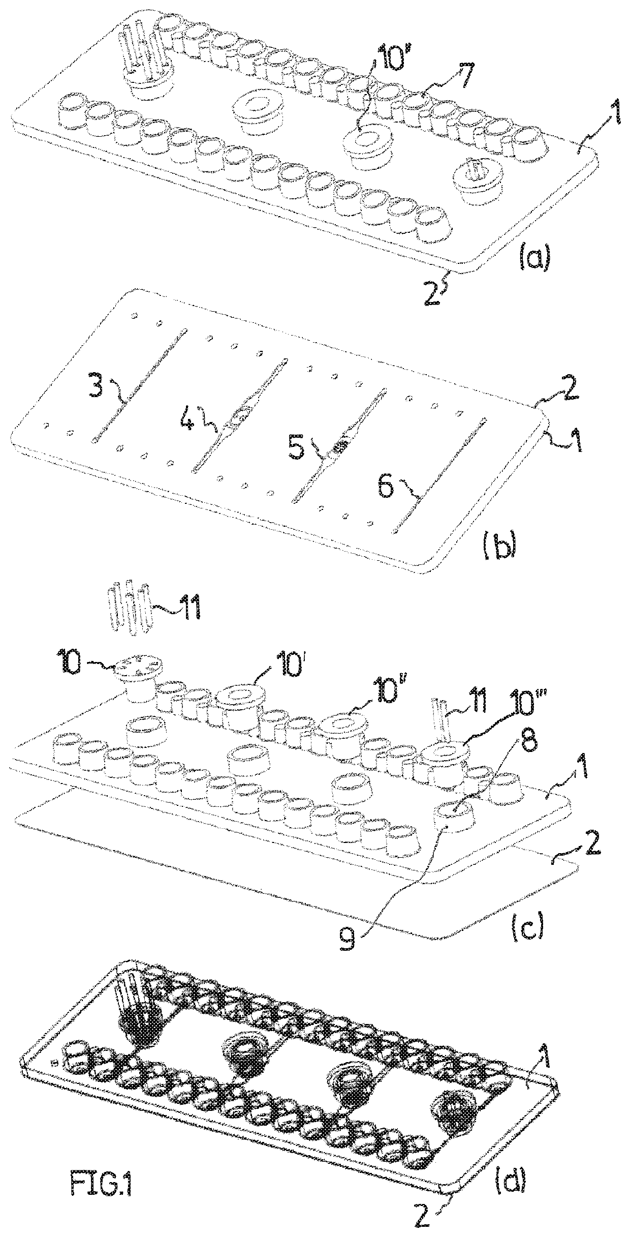
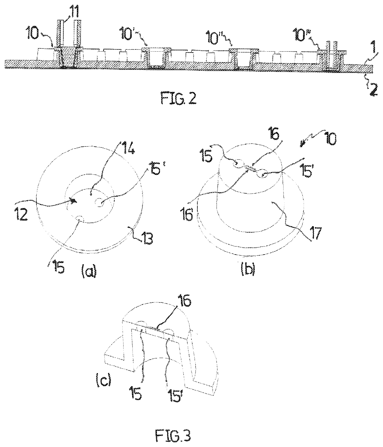
[0039]A flow cell comprises a plate-like injection molded component 1, which, for example, consists of PMMA, PC, COC, PS, PEEK, PE or PP. The injection molded component 1 is connected on one plate side to a film 2, in particular adhesively bonded or welded. Between the injection molded component 1 and the film 2, channel structures 3, 4, 5 and 6 are formed by depressions in the injection molded component and are connected to input / output ports 7 on the side of the injection molded component 1 that faces away from the film 2. Each of the channel structures 3 to 6 is assigned a passage 8 opening to the channel structure with an input connecting piece 9 projecting from the injection molded component 1. Plugs 10, 10′, 10″ and 10′″ are inserted into the passages 8 in a fluid-tight manner; as can be gathered from FIG. 2, the plug end face reaches respectively as far as the channel structure 3, 4, 5 and 6 and delimits the latter.

[0040]The designation 11 points to electric contact elements ...


PUM

PropertyMeasurementUnit
heightaaaaaaaaaa
heightaaaaaaaaaa
distanceaaaaaaaaaa

Abstract

A microfluidic flow cell including an electrode or sensor device which is located inside the flow cell and from which at least one connecting conductor leads to an externally accessible terminal contact. The electrode or sensor device is arranged on an insulated substrate member. The connecting conductor is embedded in the substrate member. The substrate member can be inserted into an opening in the flow cell such that the electrode or sensor device is placed in the flow cell.

Description

[0001]The present application is a 371 if International application PCT / EP2016 / 082748, filed Dec. 28, 2016, which claims priority of EP 161 52 755.1, filed Jan. 26, 2016, the priority of these applications is hereby claimed and these applications are incorporated herein by reference.BACKGROUND OF THE INVENTION[0002]The invention relates to a microfluidic flow cell comprising an electrode or sensor device which is arranged inside the flow cell and from which at least one connecting conductor is led to an externally accessible terminal contact. The invention also relates to a method for manufacturing such a flow cell.[0003]As is known, microfluidic flow cells (labs on a chip) are increasingly being applied in so-called life sciences, for example for the analysis of body fluids, drinking water samples or other environmental samples, preferably immediately after the sampling. For example, microfluidic flow cells are also used during the examination of food samples or the cultivation, pr...

Claims


Application Information

Patent Timeline
Patent Type & Authority Patents(United States)
IPC IPC(8): B01L3/00
CPCB01L3/502715B01L3/502707B01L2200/0689B01L2300/042B01L2300/046B01L2300/0645B01L2300/0663B01L2300/0877
Inventor WEBER, LUTZ
Owner THINXXS MICROTECHNOLOGY AG
Learn More