Supercharge Your Innovation With Domain-Expert AI Agents!

Magnetic device for capturing metal wear particles in suspension in a lubrication fluid

a technology of magnetic devices and metal wear particles, which is applied in the direction of lubricant mounting/connection, machines/engines, instruments, etc., can solve the problems of limited magnetic force of attraction, large quantity of metal particles captured by such magnetic devices, and not representative of real wear of parts

Active Publication Date: 2022-09-06
EUROCOPTER
View PDF21 Cites 2 Cited by
  • Summary
  • Abstract
  • Description
  • Claims
  • Application Information

AI Technical Summary

Benefits of technology

The invention proposes a magnetic device that can attract metal particles in at least two directions, thereby generating a maximum force of attraction. This device helps to capture metal wear particles and prevent them from causing damage.

Problems solved by technology

Since the magnetic force of attraction is not at its maximum, the quantity of metal particles captured by such magnetic devices generating a “radial” magnetic force of attraction is thus limited and not very representative of the real wear of the parts that move relative to one another and that are contained in the casing.
Nevertheless, juxtaposing two pole pieces in that way does not enable a maximum force of attraction to be generated all around the permanent magnet.
Since the magnetic force of attraction is axial only at the free end, the quantity of metal particles captured by such magnetic devices is thus likewise limited and not very representative of the real wear of the parts that move relative to one another and that are contained in the casing.
Nevertheless, such a document does not disclose a particular longitudinal dimension for the pole faces of the permanent magnet, which dimension is parallel to a longitudinal axis X. Specifically, only a particular thickness for the permanent magnet is disclosed in that document.
Thus, the magnetic force of attraction acting radially facing each of the two pole faces is not optimized, and the magnetic device does not enable all of the magnetic particles that are in suspension in the lubrication fluid to be captured.

Method used


Image

  • Magnetic device for capturing metal wear particles in suspension in a lubrication fluid
  • Magnetic device for capturing metal wear particles in suspension in a lubrication fluid
  • Magnetic device for capturing metal wear particles in suspension in a lubrication fluid

Examples


first embodiment

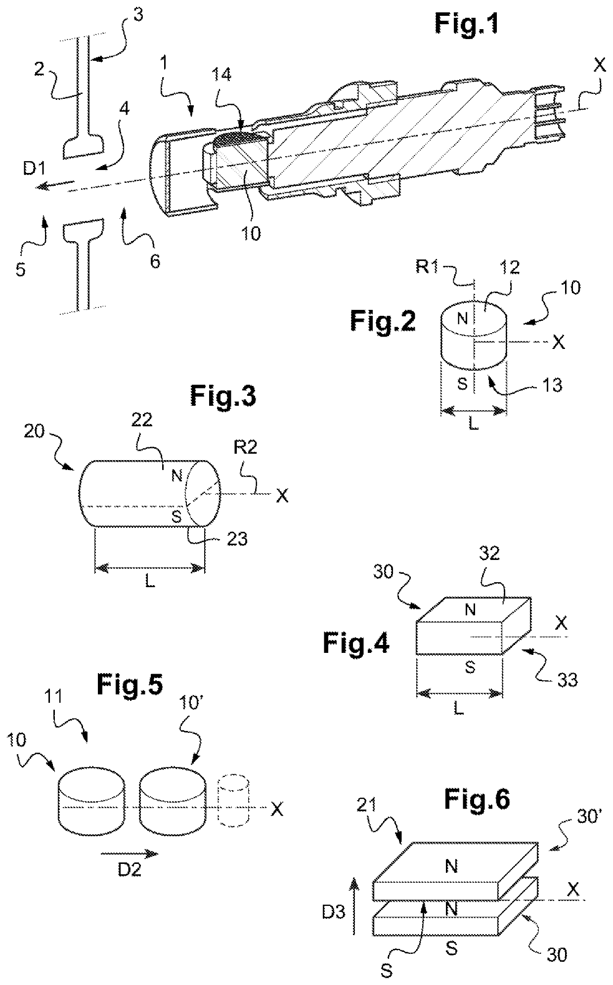
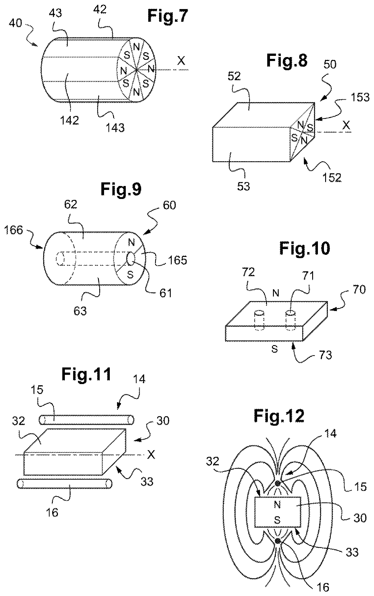
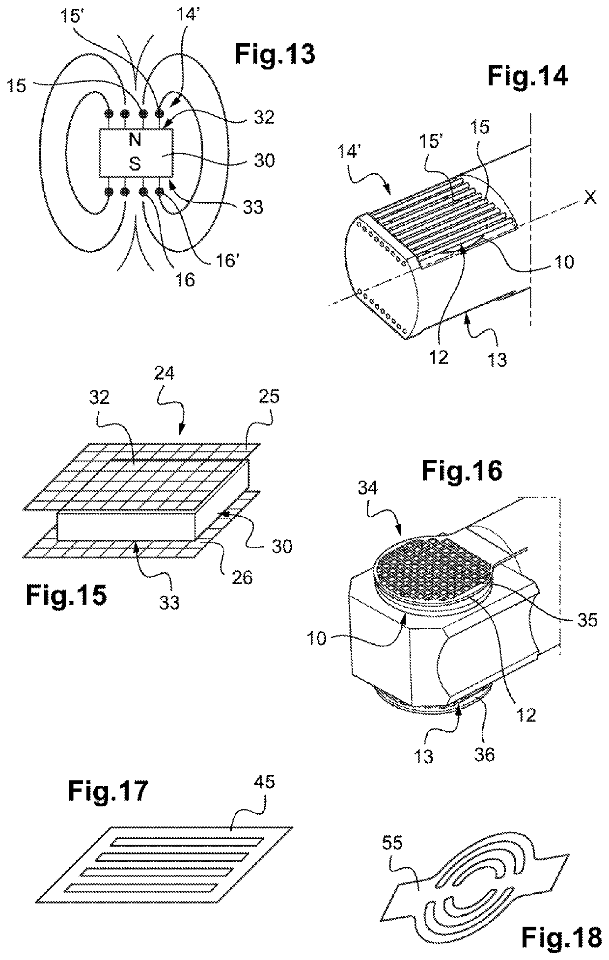
[0108]Specifically, and as shown in FIGS. 11 to 14, which correspond to the invention, the presence-detector members 14 and 14′ comprise at least two electrically conductive bars 15, 15′ and 16, 16′. Under such circumstances, a first bar 15, 15′ is then arranged facing a first pole face 12, 32 of positive polarity, and a second bar 16, 16′ is arranged facing a second pole face 13, 33 of negative polarity.

[0109]Such bars 15, 15′ and 16, 16′ may equally well be arranged parallel relative to the longitudinal axis X and they may be spaced apart by a predetermined distance respectively from the first pole face 12, 32 and from the second pole face 13, 33.

[0110]As shown in FIGS. 11 and 12, the presence-detector members 14 comprise a first bar 15 arranged facing the first pole face 32 of positive polarity, and a second bar 16 arranged facing the second pole face 33 of negative polarity.

[0111]As mentioned above, under such circumstances, the presence of metal particles is detected by the clo...

second embodiment

[0113]In the invention as shown in FIG. 15, the presence-detector member 24 for detecting metal particles comprises two groups 25 and 26 of two oriented sheets of electrically conductive wires forming e grid or an open weave textile. Also, a first group 25 is arranged facing the first pole face 32 of negative polarity, and a second group 26 is arranged facing the second pole face 33 of negative polarity.

[0114]As mentioned above, the presence of metal particles is detected by the closing of an initially-open electrical circuit between firstly one of the two groups 25 or 26 and secondly one of the two pole faces 32 or 33 of the permanent magnet 30.

third embodiment

[0115]In the invention, as shown in FIGS. 16 to 18, the presence-detector members 34 for detecting metal particles may comprise two electrically conductive perforated plates 35, 45, 55, and 36. Thus, a first place 35, 45, 55 is arranged facing the first pole face 12 of negative polarity and a second plate 36 is arranged facing a second pole face 13 of negative polarity.

[0116]As shown, the perforations in the first and second perforated plates 35, 45, 55, and 36 may present various different shapes, such as, in particular, squares, rectangles, or indeed annular portions.


PUM

PropertyMeasurementUnit
volumeaaaaaaaaaa
polaritiesaaaaaaaaaa
longitudinal dimensionaaaaaaaaaa

Abstract

A magnetic device for capturing metal wear particles in suspension in a lubrication fluid, the magnetic device being for inserting in a straight-line insertion direction of the magnetic device into a wall of a casing via a through orifice serving to put an inside volume of the casing containing the lubrication fluid into communication with an outside volume outside the casing, the magnetic device presenting a longitudinal axis X, the longitudinal axis X being for putting into coincidence with the direction for inserting the magnetic device into the casing, the magnetic device comprising a permanent magnet suitable for attracting the metal particles and a presence-detector member for detecting the metal particles attracted by the permanent magnet.

Description

CROSS-REFERENCE TO RELATED APPLICATIONS[0001]This application claims priority to French patent application No. FR 1800986 filed on Sep. 19, 2018, the disclosure of which is incorporated in its entirety by reference herein.BACKGROUND OF THE INVENTION(1) Field of the Invention[0002]The present invention relates to the field of magnetic devices serving to isolate, to hold in place, and to capture metal wear particles that are in suspension in a lubrication fluid. In particular, such a lubrication fluid may be oil for lubricating power transmission members, an engine, or any mechanical system presenting parts that move relative to one another.[0003]More precisely, such magnetic devices are generally fitted to a wall of a casing of the mechanical system bypassing through the wall. Thus, such mechanical devices can be removed from outside the casing.(2) Description of Related Art[0004]In a first type of magnetic device, and as described in Documents US 2015 / 177116, U.S. Pat. Nos. 3,869,39...

Claims


Application Information

Patent Timeline
Patent Type & Authority Patents(United States)
IPC IPC(8): B03C1/28F16N39/06F01M1/10
CPCF16N39/06B03C1/28B03C2201/20B03C2201/32F01M1/10F01M2001/1042G01N15/0656F01M11/03F01M2001/1028F16N39/005F16N2200/04G01N15/0606G01N2015/0053B03C1/288B03C1/0332B03C1/282B03C1/286B03C2201/18B03C2201/22
Inventor BASSO, BENOITLE RU, JOHNGOUJET, DAMIEN
Owner EUROCOPTER
Features
  • R&D
  • Intellectual Property
  • Life Sciences
  • Materials
  • Tech Scout
  • Unparalleled Data Quality
  • Higher Quality Content
  • 60% Fewer Hallucinations
Learn More