Microwave furnace and a method of sintering

a technology of micro-wave furnace and sintering method, which is applied in the direction of furnaces, lighting and heating apparatus, electric/magnetic/electromagnetic heating, etc., can solve the problems of furnaces, which are typically not used for some ceramic materials

Active Publication Date: 2022-09-06
3M INNOVATIVE PROPERTIES CO
View PDF19 Cites 4 Cited by
  • Summary
  • Abstract
  • Description
  • Claims
  • Application Information

AI Technical Summary

Benefits of technology

[0010]The invention is advantageous in that it allows sintering of dental ceramics, in particular zirconia, by use of microwaves without an additional heating system like electric resistant elements or burners. Further, the invention helps minimizing the sintering time for the sintering of dental ceramics, in particular zirconia. The invention is further advantageous in that the time for heating the object toward the required sintering temperature is minimized while the uniformity of any temperature gradients within the object is maximized. This is in contrast to conventional thermal sintering because microwaves typically can penetrate into the object and thereby can heat up inner and outer portions of the object independently and simultaneously (volume heating effect). The invention is advantageous in that it enables the sintering a maximized sintering quality. In particular, the invention can be used to provide a sintered ceramic material having a relatively homogeneous material structure that exhibits relatively good translucency and material strength.
[0014]In one embodiment the microwave furnace has a stand which suspends the housing. The susceptor and the sintering platform are preferably each movable and / or positionable relative to the housing. The housing may be cap-shaped, in particular may have a circumferential side wall and a top wall, and may form an opening adjacent a bottom side of the housing. In this regard the terms “top” and “bottom” refer to locations in directions further away and further toward the center of gravity of the earth, respectively. The microwave furnace may further have a base from which the stand extends. Accordingly, in this embodiment the housing is stationary and the susceptor and the platform each are movable relative to the housing and to each other. This facilitates the integration of the microwave source in the housing and electrical connection of the microwave source.
[0021]In one embodiment the susceptor has a hollow-cylindrical shape. The housing, the susceptor and the sintering platform are preferably shaped so that they movably fit into each other. Such fit (between the housing and the susceptor as well as between the susceptor and the sintering platform) is preferably a loose fit, respectively, to avoid friction between the housing and the susceptor and the susceptor and the sintering platform. Nevertheless any gap between the housing and the susceptor and / or the susceptor and the sintering platform, respectively, is preferably minimized to ensure appropriate thermal insulation of the furnace chamber. With respect to an axis of symmetry (corresponding to the longitudinal axis) of the hollow-cylindrical susceptor the susceptor and the housing as well as the susceptor and the sintering platform are preferably movable relative to each other in a dimension along the axis of symmetry or longitudinal axis. The hollow-cylindrical shape of the susceptor provides for a relatively uniform emission of heat of the (heated) susceptor toward the space inside of the susceptor.

Problems solved by technology

There are also approaches to use microwave furnaces, which however typically cannot be used for some ceramic materials, for example including zirconia, which do not significantly couple into microwaves in certain temperature ranges.

Method used


Image

  • Microwave furnace and a method of sintering
  • Microwave furnace and a method of sintering
  • Microwave furnace and a method of sintering

Examples


Embodiment Construction

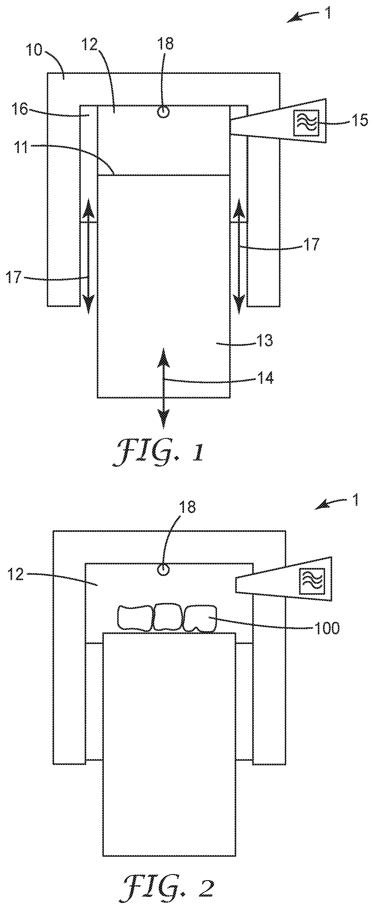
[0047]FIG. 1 shows a microwave furnace 1 according to an embodiment of the invention. The microwave furnace 1 has a housing 10, and a sintering platform 11 arranged within the housing 10. A furnace chamber 12 is formed between the housing 10 and the sintering platform 11. In the example the housing 10 is cup-shaped with the sintering platform 11 arranged within the open recess formed by the cup-shape. The housing 10 is arranged with the opening facing down (in a direction of the force of gravity). Although not illustrated in detail, the microwave furnace 1 is configured such that the housing 10 can be opened for inserting an object to be sintered into the furnace chamber 12. While the skilled person will recognize several solutions for a microwave furnace in which the chamber can be user-selectively opened or closed, in a preferred example the housing 10 is suspended at a stand (not shown) of the sintering furnace and the sintering platform 11 is vertically movable (indicated by arr...


PUM

PropertyMeasurementUnit
temperatureaaaaaaaaaa
frequencyaaaaaaaaaa
frequencyaaaaaaaaaa

Abstract

A microwave furnace has a furnace chamber formed between a chamber housing and a sintering platform for an object to be sintered. A microwave source is arranged for emitting microwaves into the furnace chamber. The microwave furnace further has a susceptor that comprises a material which over a temperature range of the material of at least 23 C to 700 C couples into microwaves. The susceptor and the furnace chamber are movable relative to each other between a first position, in which the susceptor is positioned relative to the furnace chamber, and a second position in which the susceptor is positioned further retracted from the furnace chamber relative to the first position. The invention helps providing a zirconia material with a relative homogeneous material structure.

Description

FIELD OF THE INVENTION[0001]The invention relates to a microwave furnace, and in particular to a microwave furnace having a susceptor which can be selectively positioned in and outside the furnace chamber for selectively sintering an object via microwave energy or thermal transfer (for example via thermal radiation). The invention further relates to a method of sintering.BACKGROUND ART[0002]Dental restorations are often made of or include a dental ceramic material. Dental ceramic material can provide dental restorations with a color that resembles the color of natural teeth.[0003]Dental restorations are often manufactured by using automated processes, which typically include the capturing of the shape of a patient's teeth, designing the dental restoration based on the captured shape by computer-aided design (CAD) and manufacturing the dental restoration on an automated Computer Numerical Controlled (CNC) machine or a computer controlled build-up process.[0004]A dental restoration ma...

Claims


Application Information

Patent Timeline
Patent Type & Authority Patents(United States)
IPC IPC(8): F27B17/02A61C7/12A61C13/20F27D19/00H05B6/64H05B6/80
CPCF27B17/025A61C7/12A61C13/203F27D19/00H05B6/645H05B6/6491H05B6/806H05B2206/046F27D2099/0028
Inventor HAUPTMANN, HOLGER
Owner 3M INNOVATIVE PROPERTIES CO
Why Eureka
Try Eureka