Method for producing Cu—Ni—Sn alloy and cooler to be used for same

a technology of sn alloy and cu, which is applied in the field of producing cu — ni — sn alloy and a cooler, can solve the problems of deteriorating the product quality of the alloy to be obtained, poor alloy production efficiency, and internal cracks in the ingo

Active Publication Date: 2022-09-13
NGK INSULATORS LTD
View PDF8 Cites 2 Cited by
  • Summary
  • Abstract
  • Description
  • Claims
  • Application Information

AI Technical Summary

Benefits of technology

[0009]Now the present inventors have discovered that by adopting mist cooling in which mist-like liquid is sprayed on the ingot, it is possible to provide a method for producing a Cu—Ni—Sn alloy, which reduces the internal cracks in spite of shortening the time for cooling an ingot and achieves both the productivity and the product quality.
[0010]Accordingly, an object of the present invention is to provide a method for producing a Cu—Ni—Sn alloy, which achieves both the productivity and the product quality by reducing the internal cracks in spite of shortening the time for cooling an ingot.

Problems solved by technology

For example, when the cooling speed is fast, internal cracks occur in the ingot to deteriorate the product quality of the alloy to be obtained.
By contrast, when the cooling speed is slow, the internal cracks in the ingot can be suppressed, but cooling requires a time, and therefore the productivity of the alloy to be obtained becomes poor.
For example, when the ingot is cooled with a water-cooling shower, by immersion into a water tank, or the like, which is a cooling method which has been performed in the past, the internal cracks are liable to occur in the ingot because the cooling speed is too fast.
Even when the cooling speed is slowed by, for example, air-cooling in order to suppress the occurrence of the internal cracks, cooling requires 12 hours or longer in some cases, and therefore the productivity is remarkably poor.
As described above, the internal cracks are liable to occur in a copper alloy containing Sn having a low melting point, and among the Sn-containing copper alloys, when the Cu-15Ni-8Sn alloy with a high Sn content is produced, the influence of the speed of cooling the ingot on the productivity and product quality of the alloy to be obtained is particularly large.

Method used


Image

  • Method for producing Cu—Ni—Sn alloy and cooler to be used for same
  • Method for producing Cu—Ni—Sn alloy and cooler to be used for same

Examples


example 1

Comparison

[0041]Cu-15Ni-8Sn alloy defined as UNS: C72900 was prepared as a Cu—Ni—Sn alloy and evaluated by the following procedures.

[0042](1) Weighing

[0043]A pure Cu nugget, a Nickel metal, a Sn metal, manganese tourmaline, and a Cu—Ni—Sn alloy scrap, which are raw materials for a Cu—Ni—Sn alloy, were weighed in such a way as to obtain an objective composition. That is, Cu in an amount of 163 kg, Ni in an amount of 30 kg, Sn in an amount of 15 kg, and the Cu—Ni—Sn alloy scrap in an amount of 1450 kg were weighed and mixed to be thereby formulated.

[0044](2) Melting and Slag Treatment

[0045]The weighed raw materials for a Cu—Ni—Sn alloy were melted in a high-frequency melting furnace for atmospheric air at 1200 to 1400° C. and stirred for 30 minutes to homogenize the components. Slag scraping and slag scooping were performed after completion of melting.

[0046](3) Component Analysis (Before Casting)

[0047]Part of the Cu—Ni—Sn alloy obtained by performing the melting and the slag treatment...

example 2

[0060]Preparation and evaluations of a sample were performed in the same manner as in Example 1, except that mist cooling was performed in the following manner in place of the water cooling of (5) described above. The obtained cast product had a size of 320 mm in diameter×2 m in length.

[0061](5′) Cooling (Mist Cooling)

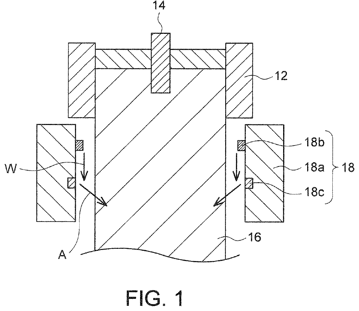
[0062]The solidified ingot 16 was continuously drawn out while mist-like water was being sprayed with the cooler 18 provided immediately below the mold 12, as schematically shown in FIG. 1. On that occasion, by discharging 7 to 13 L / min of water W from the water supply part 18b which is at the upper part of the cylindrical main body 18a of the cooler 18, and blowing air A at a pressure of 2.7 to 3.3 MPa from 120 holes each having a diameter of 3.5 mm, the holes each provided as the air ejection part 18c at the lower stage of the cylindrical main body 18a of the cooler 18, discharged water W was atomized into mist-like water (namely, mist) and was sprayed on the ingot 1...

example 3

Comparison

[0063]Preparation and evaluations of a sample were performed in the same manner as in Example 1, except that air cooling was performed in the following manner in place of the mist cooling of (5) described above. The obtained cast product had a size of 320 mm in diameter×2 m in length.

[0064](5″) Cooling (Air Cooling)

[0065]The solidified ingot was continuously drawn out while air was being blown with the cooler provided immediately below the mold. On that occasion, air was blown from 120 holes each having a diameter of 3.5 mm, the holes provided at the cylindrical main body of the cooler, and the ingot was lowered while being received with a receiving table which was lowered at a speed of 25 mm / min. By such a cooling method, the ingot was cooled to 50° C. in 12 hours after the semi-continuous casting of (4) described above. In the case of air cooling, it can be said that the speed of cooling the ingot is slow, and therefore, the internal cracks are unlikely to occur, but the...


PUM

PropertyMeasurementUnit
speedaaaaaaaaaa
temperatureaaaaaaaaaa

Abstract

There is provided a method for producing a Cu—Ni—Sn alloy by a continuous casting method or a semi-continuous casting method, the method including pouring a molten Cu—Ni—Sn alloy from one end of a mold, both ends of which are open, and continuously drawing out the alloy as an ingot from the other end of the mold while solidifying a part of the alloy, the part being near the mold; and spraying mist-like liquid on the drawn-out ingot to cool the ingot, thereby making a cast product of the Cu—Ni—Sn alloy.

Description

CROSS-REFERENCE TO RELATED APPLICATIONS[0001]This application claims priority to Japanese Patent Application No. 2020-060359 filed Mar. 30, 2020 and Japanese Patent Application No. 2021-032852 filed Mar. 2, 2021, the entire contents all of which are incorporated herein by reference.BACKGROUND OF THE INVENTION1. Field of the Invention[0002]The present invention relates to a method for producing a Cu—Ni—Sn alloy and a cooler for use in the same.2. Description of the Related Art[0003]In the past, a copper alloy, such as a Cu—Ni—Sn alloy, has been produced by a continuous casting method or a semi-continuous casting method. The continuous casting method as well as the semi-continuous casting method is one of the main casting methods and is such that a molten metal is poured into a water-cooled mold to be solidified continuously and drawn out as an ingot having a certain shape (such as a rectangular shape or a round shape), and the ingot is drawn out downward in many cases. This method pr...

Claims


Application Information

Patent Timeline
Patent Type & Authority Patents(United States)
IPC IPC(8): B22D11/124B22D11/00C22C9/06
CPCB22D11/1246B22D11/004C22C9/06B22D11/1245C22C9/02B22D11/225B22D11/049
Inventor ISHII, KENSUKE
Owner NGK INSULATORS LTD
Why Eureka
Try Eureka