Eureka AIR delivers breakthrough ideas for toughest innovation challenges, trusted by R&D personnel around the world.

High speed SAP particle applicator

a sap particle and applicator technology, applied in the field of high-speed sap particle applicators, can solve the problems of reducing the performance of any pulsing device, allowing a limited control of the pattern, and sap printing is quite inflexible with regard to changes in the pattern design

Active Publication Date: 2022-10-11
FMCG CONSULTING
View PDF8 Cites 0 Cited by
  • Summary
  • Abstract
  • Description
  • Claims
  • Application Information

AI Technical Summary

Benefits of technology

[0020]A4—a screen positioned between the inner revolving drum and the outer shell revolving drum, optionally connected to said holes of said outer drum or rotatably mounted wherein the screen comprises apertures adapted to the particle size of the SAP and preventing at least 95% of the SAP granules to not penetrate there through.

Problems solved by technology

Methods of this kind only allow a limited control of the pattern and the distribution of the local basis weight of the SAP over the area over which the SAP is distributed.
Placing the nozzle far away from the pulp / SAP blending process significantly reduces the performance of any pulsing device.
This SAP printing, however, is quite inflexible with regard to changes in the pattern design.
Furthermore, such systems do not allow the use of multiple types of SAP particles or only with significant complications.
Such a system for distributing different types of SAP in different regions of the absorbent article would have significant cost and environmental benefits.
The fluidized bed apparatus and methodology, although functional is has some process disadvantages in that (i) the secondary fluidized bed disturbs SAP pre-filled holes on the print-roll leading to cross contamination of SAP and also reduces the metering accuracy of the process (ii) the fluidized bed actually segregates the SAP particles causing an un-even particle size distribution, (iii) requires energy, (iv) creates exhaust air that exits the system that has to be managed via the linking to air filtration systems, (v) does not fully fluidize the SAP across the entire surface of SAP coming in contact with the print-roll thereby slightly damaged the surface of the SAP that comes into contact with the print-roll.

Method used


Image

  • High speed SAP particle applicator
  • High speed SAP particle applicator
  • High speed SAP particle applicator

Examples


Embodiment Construction

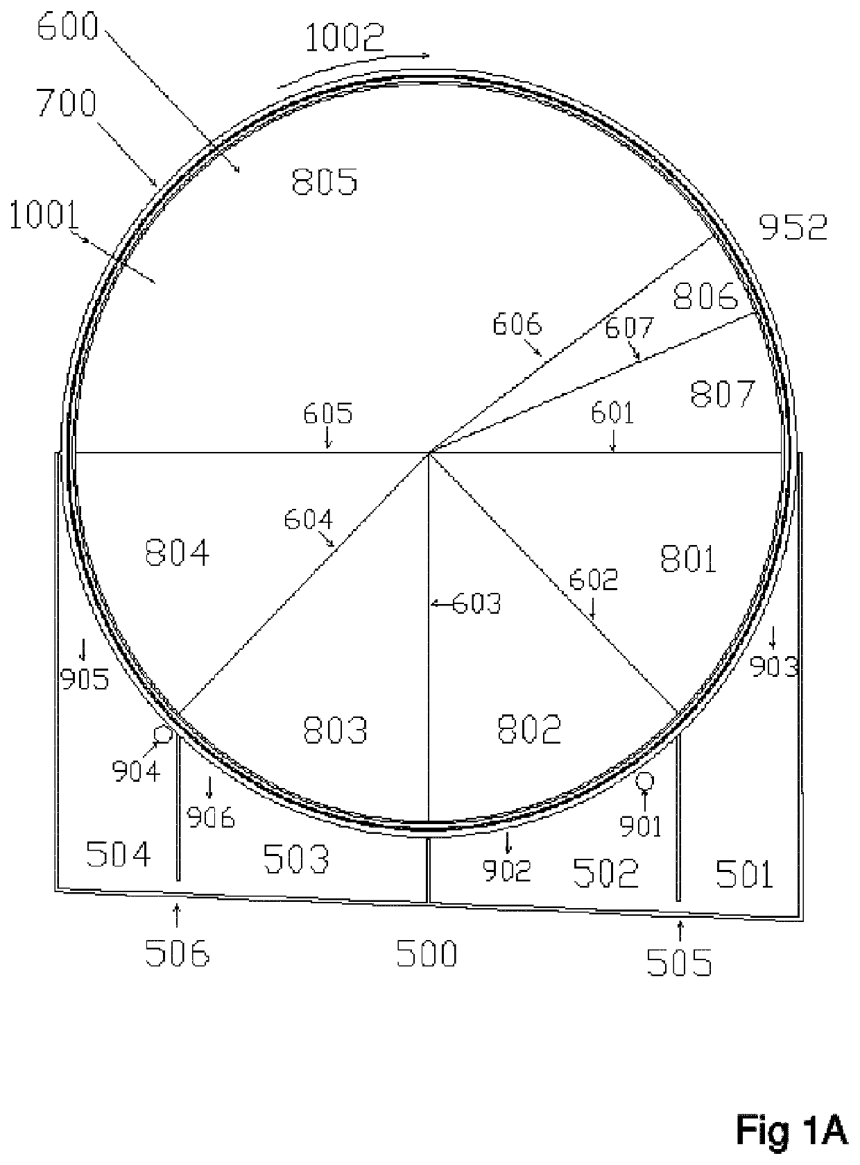
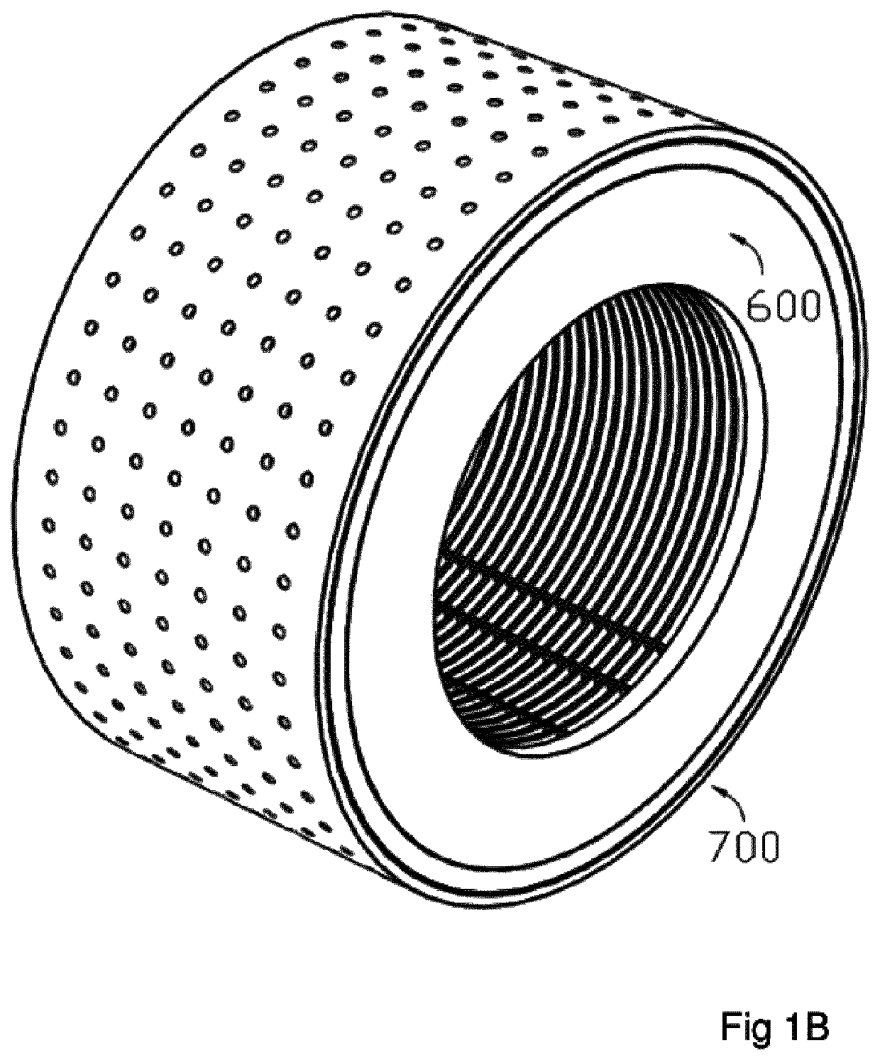
[0054]Thus the present invention is directed to an equipment and a method for applying one or more types of SAP particles or SAP granules as may be referred to interchangeably, into an air stream or onto a surface with high accuracy of the distribution (pattern), amount and composition of SAP material by a transfer device, as may be referred to interchangeably as pick and place device with the respective method using a rotating drum with holes. Such a process method may be used in an application of SAP particles requiring accurate, print like positioning of granules or particles on a carrier layer. One particular application may be the making of primarily SAP comprising cores for disposable diapers or parts of such cores, wherein the SAP is immobilized such as by glue.

[0055]According to a first aspect of the present invention, the transfer method according to the invention comprises the following process steps:

[0056]SAP granules are provided and positioned close to a rotating SAP tr...


PUM

PropertyMeasurementUnit
speedaaaaaaaaaa
speedaaaaaaaaaa
surface speedsaaaaaaaaaa

Abstract

The present invention relates to an apparatus and a method of applying a single SAP (Super Adsorbent Polymer) type granules or multiple SAP types at high speed in a continuous or intermittent 2-dimensional or 3-dimensional profile via volumetric or gravimetric metering onto a receiving system such as a carrier layer and / or into an air stream for use in an absorbent article, particularly diapers for babies or adults, training pants, pull-up diapers (diaper pants), sanitary napkins, panty liners or the like. These articles typically comprise of a carrier layer with the SAP particles and / or a mixed SAP and fiber core together with further layers, making up the complete article.

Description

FIELD OF THE INVENTION[0001]The present invention relates to an apparatus and a method of applying single SAP (Super Absorbent Polymer) type granules or multiple SAP type granules at high speed in a predetermined continuous or intermittent profile onto a carrier layer or into an air stream, e.g. for use in the manufacture of an absorbent article, such as diapers for babies or adults, training pants, pull-up diapers (diaper pants), sanitary napkins, panty liners or the like. These articles typically comprise a carrier layer with the SAP particles and / or a mixed SAP and fiber core together with further layers, as may be combined with further elements for making up the complete article.BACKGROUND OF THE INVENTION[0002]The term “SAP” granules or particles as used herein interchangeably include materials capable of absorbing and storing a high amount of liquid compared with the volume thereof. “SAP” is the abbreviation of Super Absorbing polymer. In the present context, the SAP material ...

Claims


Application Information

Patent Timeline
Patent Type & Authority Patents(United States)
IPC IPC(8): B05D1/22A61F13/15B05D1/24A61F13/00
CPCA61F13/15658B05D1/24A61F2013/15821
Inventor SCAIFE, MARTIN
Owner FMCG CONSULTING
Why Eureka
Eureka Blog
Learn More