Eureka AIR delivers breakthrough ideas for toughest innovation challenges, trusted by R&D personnel around the world.

Vehicle electronic control device

a technology of electronic control device and in-vehicle battery, which is applied in the direction of electric devices, battery/fuel cell control arrangement, transportation and packaging, etc., can solve the problems of long time from the completion of the battery charge to the disconnection of the charge cable, and the uncertain period from the completion of the battery charge to the turning on of the ground power supply switch, so as to achieve the effect of preventing the wasteful discharge of the in-vehicle battery and being convenient to execu

Active Publication Date: 2022-10-11
MITSUBISHI ELECTRIC CORP
View PDF21 Cites 0 Cited by
  • Summary
  • Abstract
  • Description
  • Claims
  • Application Information

AI Technical Summary

Benefits of technology

[0011]The present invention provides an activation signal processing unit provided with a plurality of activation command elements so as to be able to greatly suppress a standby current generated in an entire arithmetic control unit. The arithmetic control unit, which is supplied with power from an in-vehicle battery through a power supply relay configured to respond to a closing operation of a power supply switch so as to execute drive control for a main electric apparatus, is configured to be activated so as to apply drive control to an auxiliary electric apparatus in response to closing operations of the plurality of activation command elements even when the power supply switch is opened. In particular, the present invention provides an in-vehicle electronic control device including an activation signal processing unit suitable for charge control to be applied to an electric vehicle.
[0016]Thus, when the activation command element is, for example, a push button switch, and a depression operation is executed for a relatively short period, even when the depression period is shorter than a voltage rise period of the stabilized power supply and an inactive period of the arithmetic control unit required for a self-diagnosis required period, the composite activation signal can certainly be generated by the activation latch unit to activate the arithmetic control unit. Before the arithmetic control unit stops the operation, the composite activation signal can be released by the cutoff latch unit. Therefore, the following effect is provided. Various types of auxiliary control can easily be executed by the arithmetic control units even at a time point at which the power supply switch is not closed. There is also provided such an effect that an unnecessary power supply state is not generated so that a wasteful discharge of the in-vehicle battery can be prevented, by releasing the composite activation signal at a time point at which the auxiliary control by the arithmetic control unit is completed even when a short-circuit abnormality occurs in the push button switch, or the activation command element executes an uncertain long-period closing operation.
[0017]Moreover, when the closed activation command element is once opened, the recovery determination unit releases the cutoff operation by the cutoff latch unit. Thus, when the activation command element executes the uncertain long period closing operation, the auxiliary control is enabled again by the activation command element being closed again, and the cutoff latch unit is activated so as to execute power saving operation during the closing operation for a long period. Therefore, the following effect is provided. The common individual activation processing units can be applied even when the activation command elements are different from one another in operation characteristics.

Problems solved by technology

Thus, the capacity of a program memory for a main CPU, which is a microprocessor forming the in-vehicle electronic control device, is huge, and a start delay period required for a start inspection therefor and an after-run period required for processing of saving current state before operation stop increase.
Meanwhile, in WO 2013 / 054387 A1, attaching and detaching the charge cable and turning on and off of the ground power supply switch are manual operations, and hence a period from the connection of the charge cable to the turning on of the ground power supply switch may be an uncertain long period.
Further, a period from the completion of the charge of the battery to the disconnection of the charge cable may also be an uncertain long period.

Method used


Image

  • Vehicle electronic control device
  • Vehicle electronic control device
  • Vehicle electronic control device

Examples


first embodiment

Detailed Description of First Embodiment

(1) Detailed Description of Configuration

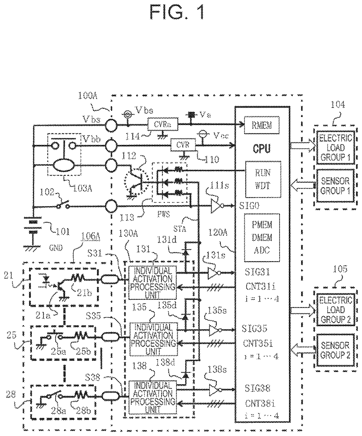
[0037]A detailed description is now given of a configuration of FIG. 1, which is an overall circuit block diagram of an in-vehicle electronic control device including an activation signal processing unit according to a first embodiment of the present invention.

[0038]In FIG. 1, an in-vehicle battery voltage Vbs is applied from an in-vehicle battery 101 of, for example, a DC-12 V system to the in-vehicle electronic control device 100A. A drive power supply voltage Vbb is applied through a power supply relay 103A, which is energized when a power supply switch 102 is closed. Moreover, a main electronic apparatus 104 controlled to drive when the power supply switch 102 is closed is connected to the in-vehicle electronic control device 100A. The main electric apparatus 104 is formed of an electric load group 1 and a sensor group 1.

[0039]An auxiliary electronic apparatus 105 controlled to drive when the power ...

second embodiment

Detailed Description of Second Embodiment

(1) Detailed Description of Configuration

[0166]A detailed description is now given of a configuration of FIG. 7, which is an overall circuit block diagram of an in-vehicle electronic control device including an activation signal processing unit according to a second embodiment of the present invention with a focus on differences from FIG. 1.

[0167]In FIG. 7, an in-vehicle battery voltage Vbs is applied from the in-vehicle battery 101 of, for example, a DC-12 V system to an in-vehicle electronic control device 100B. A drive power supply voltage Vbb is applied through a power supply relay 103B, which is energized when the power supply switch 102 is closed. Moreover, the main electronic apparatus 104 controlled to drive when the power supply switch 102 is closed is connected to the in-vehicle electronic control device 100B.

[0168]The main electric apparatus 104 includes a travel control unit including a drive power conversion circuit 210 and a coo...

third embodiment

Detailed Description of Third Embodiment

(1) Detailed Description of Configuration

[0285]A detailed description is now given of configurations of FIG. 12, which is an overall circuit block diagram of an in-vehicle electronic control device including an activation signal processing unit according to the third embodiment of the present invention, and FIG. 13, which is an overall circuit diagram relating to the activation signal processing unit of FIG. 12 with a focus on differences from FIG. 1.

[0286]In FIG. 12, an in-vehicle battery voltage Vbs is applied from the in-vehicle battery 101 of, for example, a DC-12 V system to an in-vehicle electronic control device 100C. A drive power supply voltage Vbb is applied through a power supply relay 103C, which is energized when the power supply switch 102 is closed. Moreover, the main electronic apparatus 104 controlled to drive when the power supply switch 102 is closed is connected to the in-vehicle electronic control device 100C.

[0287]The mai...


PUM


Abstract

A standby current of an arithmetic control unit configured to execute a control operation based on an activation signal generated by an uncertain manual operation is suppressed. A power supply relay configured to supply power to an arithmetic control unit is driven so as to be closed by a power supply switch, to thereby apply drive control to a main electric apparatus, and apply drive control to an auxiliary electric apparatus in accordance with a composite activation signal generated by an activation signal processing unit responding to closing operations of activation command elements even when the power supply switch is opened. As a result, a standby current generated in the activation signal processing unit is greatly suppressed compared with a case in which the arithmetic control unit is intermittently activated.

Description

BACKGROUND OF THE INVENTION1. Field of the Invention[0001]The present invention relates to improvement of an in-vehicle electronic control device including an activation signal processing unit configured to be supplied with power from an in-vehicle battery for control to execute drive control for a main electric apparatus during a period in which a power supply switch for vehicle driving is closed to be in a conductive state, and to be able to execute drive control for an auxiliary electronic control device even when the power supply switch is opened to be in a cutoff state. In particular, the present invention relates to improvement of an activation signal processing unit of an in-vehicle electronic control device suitable for a case in which the main electric apparatus is a motor controller configured to supply power from an in-vehicle main battery to drive a motor for traveling of an electric vehicle, and the auxiliary electric apparatus is a charge control unit configured to cha...

Claims


Application Information

Patent Timeline
Patent Type & Authority Patents(United States)
IPC IPC(8): B60L53/60B60L58/12B60L53/16
CPCB60L53/60B60L53/16B60L58/12B60R16/0231Y02T90/16Y02T90/12B60L3/04B60L53/14B60L53/67Y02T10/92
Inventor KANZAKI, SHOZOISHIDA, YOSHIKAZU
Owner MITSUBISHI ELECTRIC CORP
Why Eureka
Eureka Blog
Learn More