Rotor for an electric drive machine for driving a compressor, a turbine or a charger shaft of a turbocharger, and turbocharger comprising an electric drive machine and such a rotor

a technology of electric drive machine and charger shaft, which is applied in the direction of machines/engines, gas turbine plants, combustion engines, etc., can solve the problems of high rotation speed of exhaust-gas turbocharger, negative consequences of bearing load, and additional load on the turbocharger shaft and associated bearing bushings

Active Publication Date: 2022-10-11
ROBERT BOSCH GMBH
View PDF15 Cites 1 Cited by
  • Summary
  • Abstract
  • Description
  • Claims
  • Application Information

AI Technical Summary

Benefits of technology

[0007]An important technical correlation in the context of development of an electric drive unit of an electrically assisted exhaust-gas turbocharger is to be seen in the ratio between the torque of the electric drive unit and the moment of inertia of the rotating group of the turbocharger. The mass of the rotor of the electric drive unit which is installed on the turbocharger shaft results in an additional load on the turbocharger shaft and on the associated bearing bushings, as compared with an exhaust-gas turbocharger having no electric drive unit. The high rotation speed of the exhaust-gas turbocharger presents particular difficulties. It is important for the entire assemblage to be mechanically and electrically stable even at high rotation speeds. The mass of the entire rotating assemblage installed on the turbocharger shaft is increased by the additional mass of the rotor. This means not only an increase in the moment of inertia of the turbocharger, but also a shift in the center of mass almost to the center of one of the bearing bushings of the turbocharger shaft. This effect can have negative consequences in terms of the resulting bearing load, since the surface pressure in the two running surfaces of the bearing bushings can vary considerably.
[0024]Advantageously, the axial clamping force acting in the direction of the rotation axis can press the rotor body against a compressor wheel of the compressor, and press the compressor wheel against a stop on the turbocharger shaft. An axial preload onto the compressor wheel can thus be effected by way of the rotor. The axial force advantageously serves for correctly positioned immobilization of the compressor wheel at high rotation speeds.

Problems solved by technology

The mass of the rotor of the electric drive unit which is installed on the turbocharger shaft results in an additional load on the turbocharger shaft and on the associated bearing bushings, as compared with an exhaust-gas turbocharger having no electric drive unit.
The high rotation speed of the exhaust-gas turbocharger presents particular difficulties.
This effect can have negative consequences in terms of the resulting bearing load, since the surface pressure in the two running surfaces of the bearing bushings can vary considerably.
In addition to the problems associated with torques and moments of inertia, heat flow from the turbine into the bearing bracket represents a further challenge.
In gasoline engines in particular, in the worst case this heat flow can cause the permanent magnets of the rotor to become demagnetized.

Method used


Image

  • Rotor for an electric drive machine for driving a compressor, a turbine or a charger shaft of a turbocharger, and turbocharger comprising an electric drive machine and such a rotor
  • Rotor for an electric drive machine for driving a compressor, a turbine or a charger shaft of a turbocharger, and turbocharger comprising an electric drive machine and such a rotor
  • Rotor for an electric drive machine for driving a compressor, a turbine or a charger shaft of a turbocharger, and turbocharger comprising an electric drive machine and such a rotor

Examples


Embodiment Construction

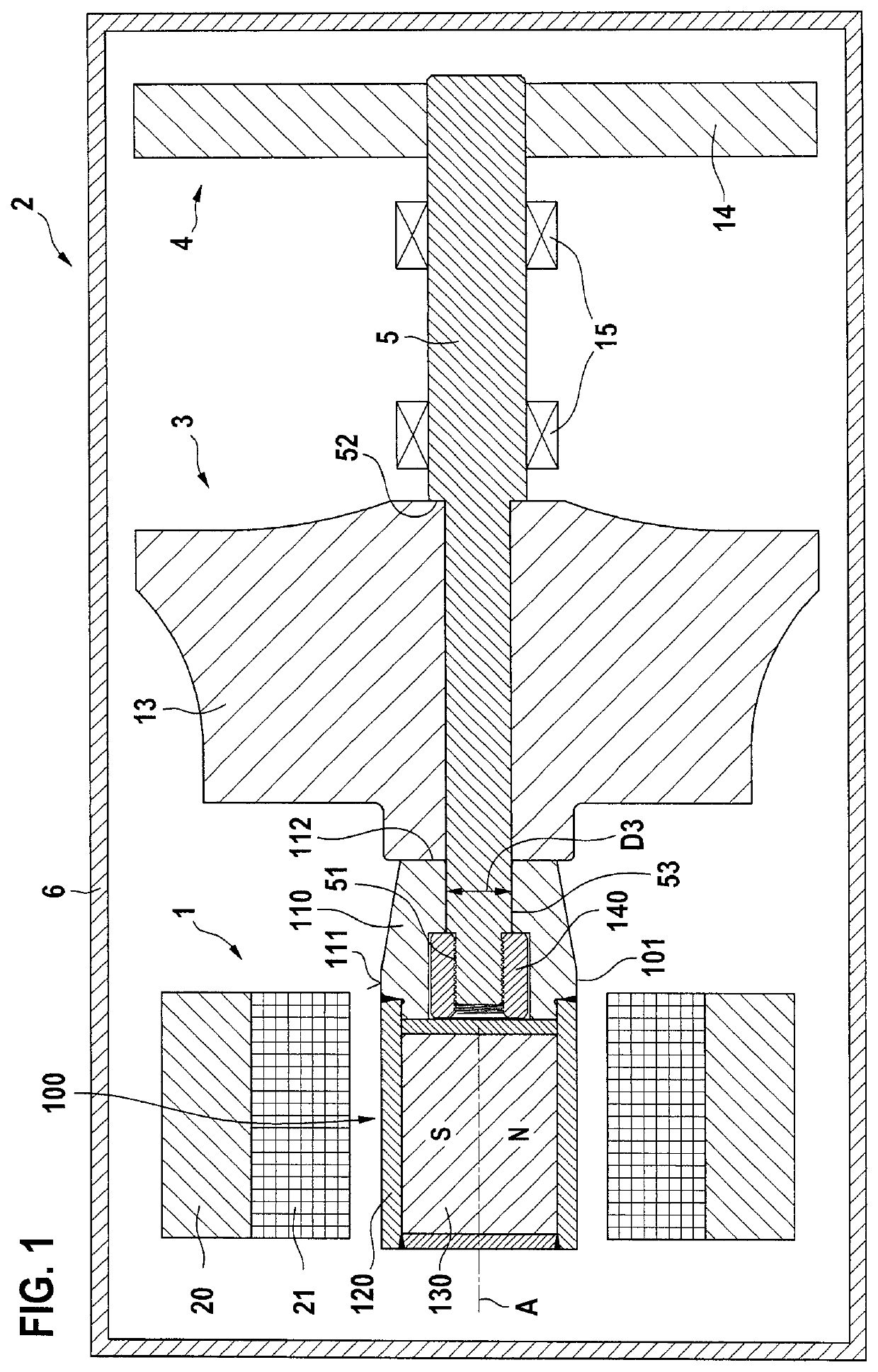
[0032]FIG. 1 is a longitudinal section through an exhaust-gas turbocharger 2 of an internal combustion engine, having an electric drive unit 1. The exhaust-gas turbocharger encompasses a housing 6, depicted here merely schematically, which in particular can also be embodied in multiple parts with a bearing housing, a compressor housing (not depicted) and a turbine housing. The exhaust-gas turbocharger encompasses a compressor 3 and a turbine 4. A compressor wheel 13 of compressor 3, and a turbine wheel 14 of turbine 4, are schematically shown in FIG. 1. Compressor wheel 13 and turbine wheel 14 can be disposed nonrotatably on a shared turbocharger shaft 5. Turbocharger shaft 5 is mounted rotatably around a rotation axis A in bearing bushings 15 in housing 6 of exhaust-gas turbocharger 2.

[0033]Turbine 4 can be understood as a rotating flow machine that is configured to convert a drop in the internal energy of a flowing fluid into a mechanical power output that it delivers via turbocha...


PUM


Abstract

An exhaust-gas turbocharger having an electric drive unit for driving a compressor, a turbine, or a turbocharger shaft of the exhaust-gas turbocharger. The electric drive unit has a rotor and a stator. The rotor is equipped with a rotor body embodied around a rotation axis of the rotor. A receptacle for at least one permanent magnet is embodied on the rotor body. A permanent magnet is disposed in the receptacle of the rotor body. The rotor body is mountable using a threaded bushing on a turbocharger shaft of the exhaust-gas turbocharger. The rotor body has a further receptacle which extends in the direction of the rotation axis and in which the threaded bushing is disposed inside the rotor body. The further receptacle is disposed in the rotor body with an offset in the direction of the rotation axis relative to the receptacle.

Description

BACKGROUND INFORMATION[0001]A variety of electric drive units for an exhaust-gas turbocharger are available in the related art. German Patent Application No. DE 10 2017 207 532 A1, for example, describes an exhaust-gas turbocharger having an electric drive unit. Exhaust-gas turbochargers of this kind are used in particular in automotive engineering to increase the air charge in cylinders of an internal combustion engine, in order to enhance the performance of the internal combustion engine. An exhaust-gas turbocharger is equipped with an electric drive unit in order to drive the turbocharger shaft of the exhaust-gas turbocharger on which a compressor wheel as well as a turbine wheel are disposed. By way of the electric drive unit, aspirated fresh air can be compressed, and delivered to the internal combustion engine with elevated boost pressure, independently of an exhaust-gas flow of the internal combustion engine. Boost pressure buildup, which is otherwise delayed in time, can the...

Claims


Application Information

Patent Timeline
Patent Type & Authority Patents(United States)
IPC IPC(8): F02B37/10F01D5/04F01D15/10F02C6/12F02B37/12
CPCF02B37/10F01D5/043F01D15/10F02C6/12F02B2037/122F05D2220/40F05D2220/768Y02T10/12
Inventor SZULCZYNSKI, HUBERTSCHEPP, RENE
Owner ROBERT BOSCH GMBH
Why Eureka
Try Eureka