Full power blow-back gun for lightweight application
- Summary
- Abstract
- Description
- Claims
- Application Information
AI Technical Summary
Benefits of technology
Problems solved by technology
Method used
Image

Examples
Embodiment Construction
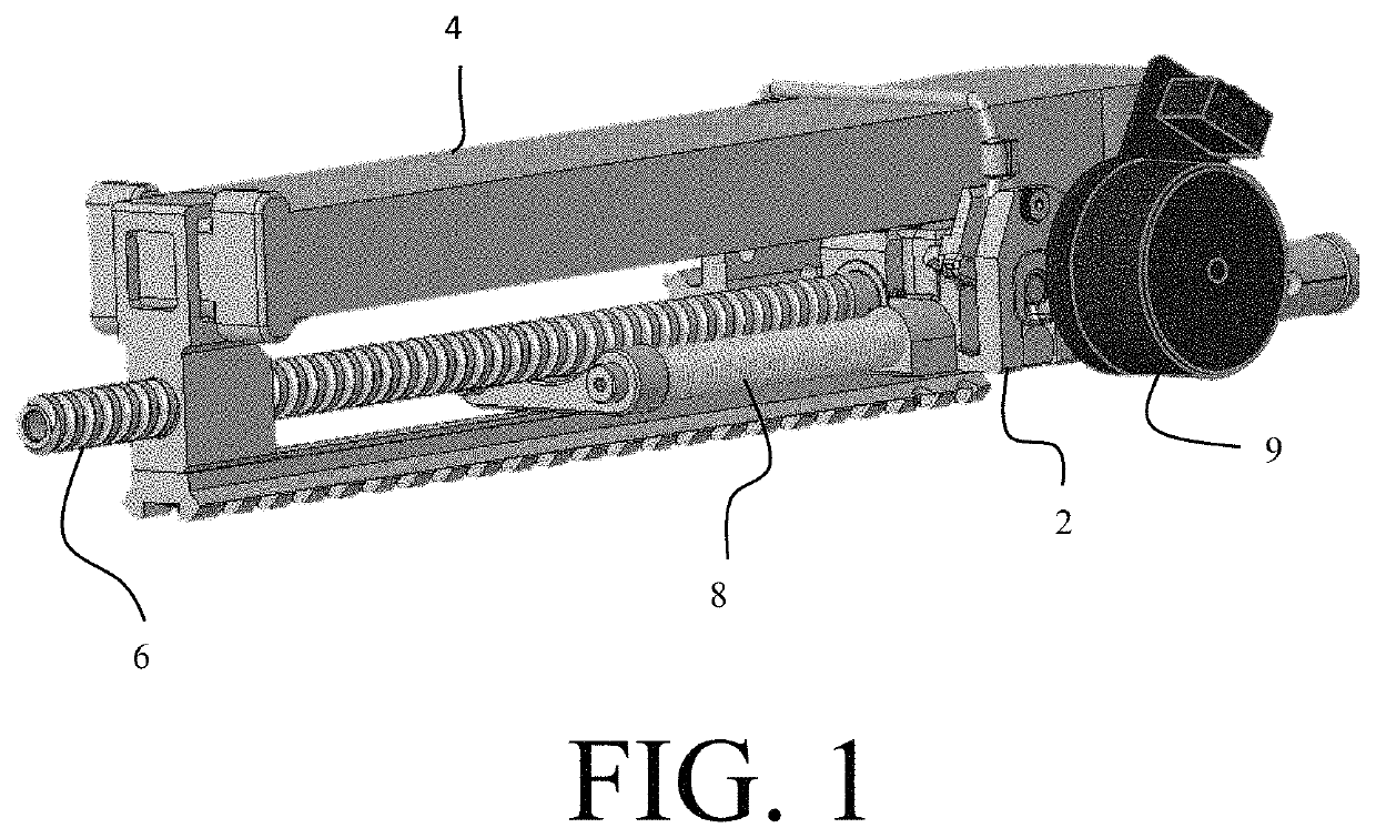
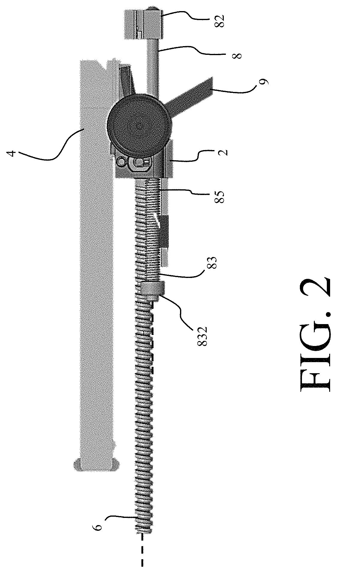
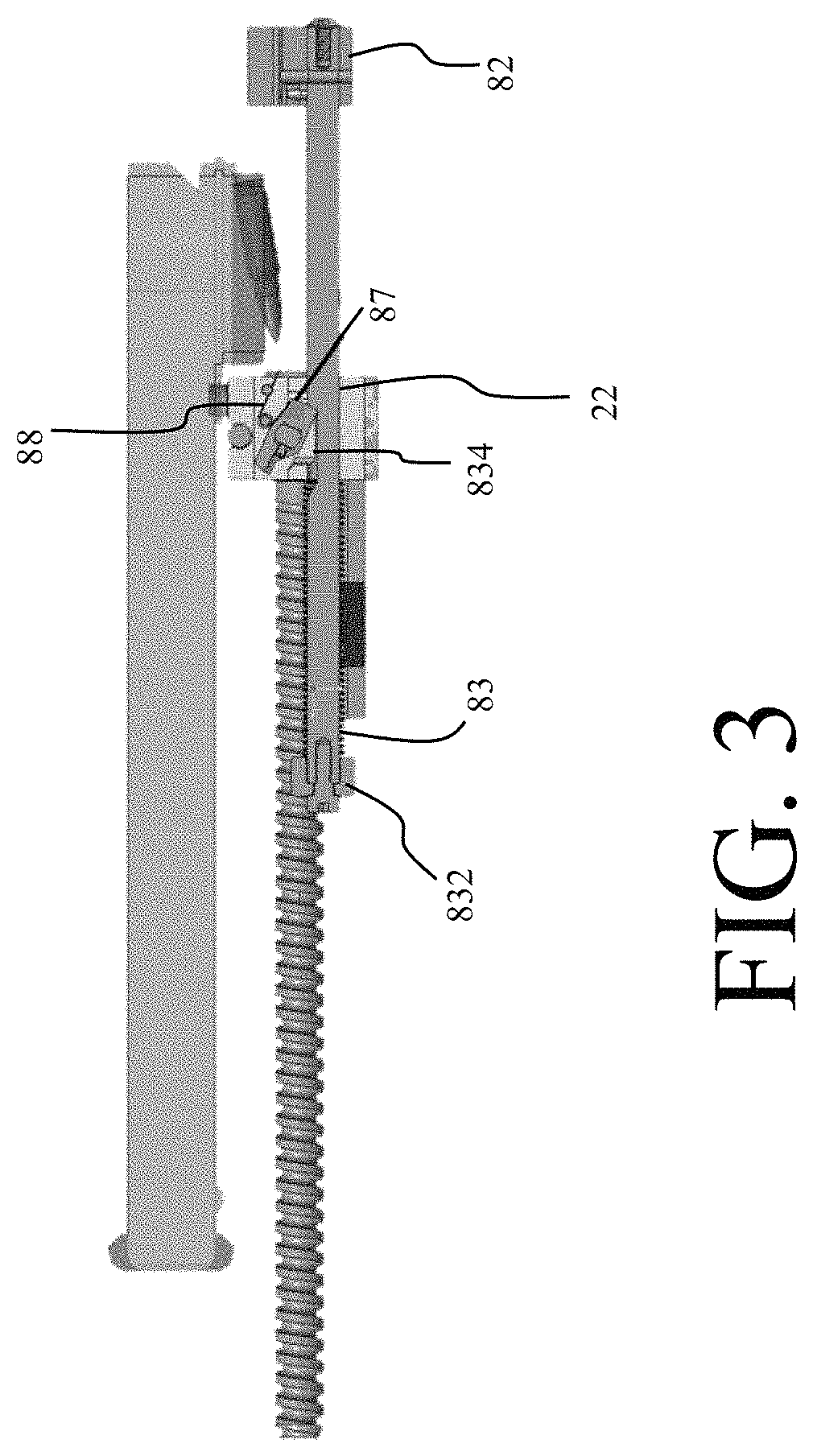
[0023]A weapon system for use on a lightweight unmanned aerial vehicle (UAV) employs blowback operation to provide lightweight and reliable lethality. The weapon system enables firing of high power centerfire rifle cartridges from the lightweight UAV without the need for an overly massive bolt. The weapon system achieves this through several design features which will be described in more detail below. Additionally, the weapon system is configured such that it will not fire due to a crash landing.
[0024]The weapon system is particularly suited for use on a lightweight UAV. In this context, lightweight UAV denotes a UAV which is soldier-portable. For example, the weapon system is particularly suited for Group 1 and Group 2 UAVs as classified by the United States Department of Defense. Group 1 UAVs are classified as UAVs which weigh between 0 and 20 pounds and have an operating altitude of less than 1200 feet above ground level (AGL). Group 2 UAVs are generally classified as being betw...
PUM
 Abstract
Description
Claims
Application Information