Vehicle and charging system

a charging system and vehicle technology, applied in the direction of electric propulsion mounting, coupling device connection, transportation and packaging, etc., can solve the problem that the charger may not perform the feedback control when charging is stopped

Active Publication Date: 2022-11-01
TOYOTA JIDOSHA KK
View PDF16 Cites 0 Cited by
  • Summary
  • Abstract
  • Description
  • Claims
  • Application Information

AI Technical Summary

Benefits of technology

[0007]When the unlocked state is detected, the vehicle reduces the required current value to the charging station.
[0011]On the other hand, when the charging connector is in the unlocked state, the charging connector may be pulled out, such that there is a need to reduce the current output from the charging station in a short time.
[0012]The present disclosure has been made in a view of the problems, and an object thereof is to provide a vehicle and a charging system that can reduce an output current in a short time when it is detected that a charging connector is in an unlocked state during charging.
[0019]With the vehicle and the charging system according to the present disclosure, the output current can be reduced in a short time when it is detected that the charging connector is in the unlocked state during charging.

Problems solved by technology

The charger may not perform the feedback control when charging is stopped.

Method used


Image

  • Vehicle and charging system
  • Vehicle and charging system
  • Vehicle and charging system

Examples


first embodiment

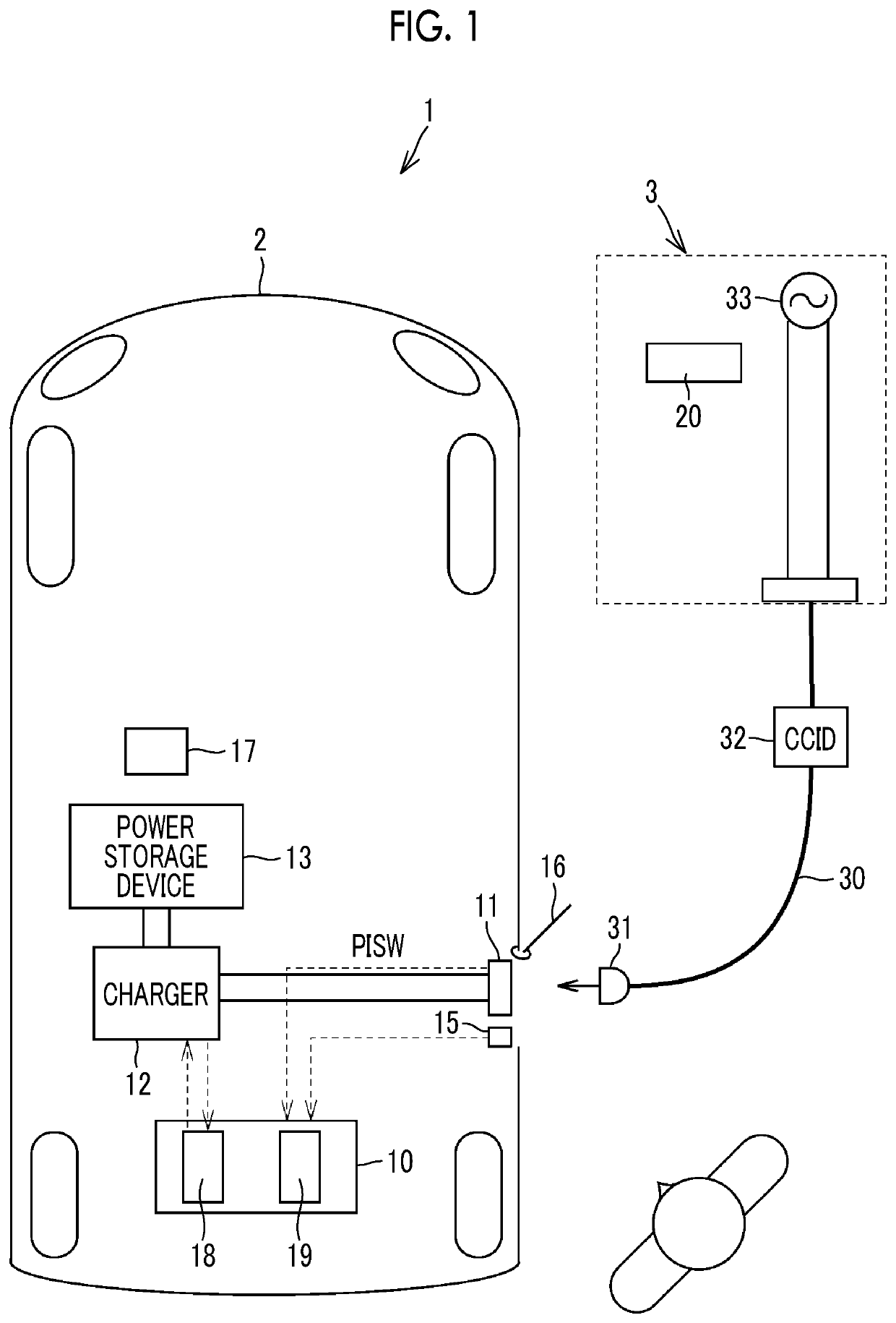
[0035]FIG. 1 is a block diagram schematically showing a charging system 1 according to a first embodiment. The charging system 1 includes a vehicle 2 and a charging station 3. The vehicle 2 includes a controller 10, an inlet 11, a charger 12, a power storage device 13, a lock device 15, and a battery electronic control unit (ECU) 17.

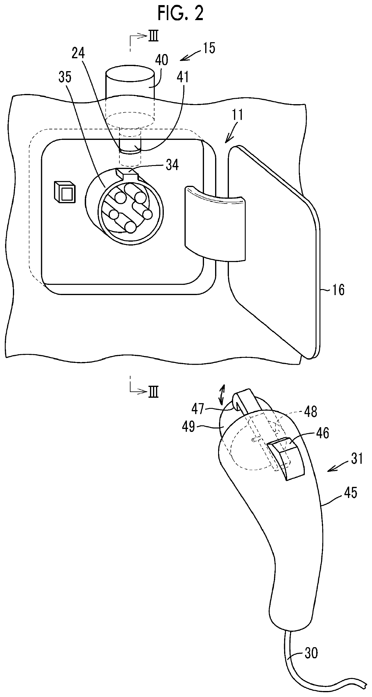
[0036]The inlet 11 is a connection portion to which a charging connector 31 provided in the charging station 3 is connected. Note that, the vehicle 2 is provided with a lid 16, and by opening the lid 16, the inlet 11 is exposed to the outside and the charging connector 31 can be connected.

[0037]The charger 12 is, for example, a converter such as an AC to DC converter. The charger 12 converts an alternating current power supplied through the inlet 11 into a direct current power and supplies the direct current power to the power storage device 13.

[0038]The power storage device 13 is a secondary battery such as a lithium-ion battery or a capacitor. The powe...

second embodiment

[0100]A charging system according to a second embodiment will be described mainly with reference to FIGS. 11 to 13. Since a configuration of the charging system according to the second embodiment and a configuration of the charging system 1 according to the first embodiment are substantially the same, the description will be made with reference to FIG. 1 or the like as appropriate.

[0101]In the charging system according to the second embodiment, the control during charging (Step St2) shown in FIG. 6 is different from that in the first embodiment.

[0102]FIG. 11 is a flowchart showing the control during charging in the second embodiment. In FIG. 11, the controller 19 sets the upper limit power value Plim3 and a flag F3 (Step St14A). FIG. 12 is a flowchart showing Step St14A.

[0103]As shown in FIG. 12, when the controller 19 determines that the charging connector 31 is in the locked state (Yes in Step St44), the flag F3 is turned to “OFF” (Step St46A). Then, the upper limit power value Pl...


PUM


Abstract

The vehicle includes an inlet configured to be connected to a charging connector provided in a charging station, a lock device configured to switch between a locked state where the charging connector is locked to the inlet and an unlocked state where the charging connector is removable from the inlet, a power storage device configured to be charged with an electric power supplied through the charging connector, and a control device configured to control charging of the power storage device. In a state where the charging connector is connected to the inlet and the power storage device is being charged, the control device stops charging when the lock device is in the unlocked state.

Description

CROSS-REFERENCE TO RELATED APPLICATION[0001]This application claims priority to Japanese Patent Application No. 2020-033528 filed on Feb. 28, 2020, incorporated herein by reference in its entirety.BACKGROUND1. Technical Field[0002]The present disclosure relates to a vehicle and a charging system.2. Description of Related Art[0003]Conventionally, various vehicles that can charge a power storage device with an electric power supplied from a charging station have been proposed.[0004]For example, a vehicle described in Japanese Unexamined Patent Application Publication No. 2019-47544 (JP 2009-47544 A) includes an inlet to which a charging connector of a charging station is connected, a lock device that locks the charging connector to the inlet, and a power storage device.[0005]In a state where the charging connector is connected to the inlet and the power storage device is being charged, the vehicle requests the charging station to supply a current having a first current value when the ...

Claims


Application Information

Patent Timeline
Patent Type & Authority Patents(United States)
IPC IPC(8): B60L53/16H02J7/00B60L53/60
CPCB60L53/16B60L53/60H02J7/0045B60L53/18B60K1/04H02J7/0036H01R13/6397H01R2201/26Y02T10/70Y02T10/7072Y02T90/12Y02T90/14
Inventor KOJIMA, KOICHIMASE, TAKAHIKO
Owner TOYOTA JIDOSHA KK
Why Eureka
Try Eureka