Propeller and method in which a propeller is set into motion

Active Publication Date: 2022-11-08
MAX PLANCK GESELLSCHAFT ZUR FOERDERUNG DER WISSENSCHAFTEN EV
View PDF25 Cites 0 Cited by
  • Summary
  • Abstract
  • Description
  • Claims
  • Application Information

AI Technical Summary

Benefits of technology

[0028]Preferably, at least 20%, more preferably at least 50%, more preferably at least 80%, more preferably at least 95% of the surface area of the propellers has a surface roughness Ra (pursuant to Deutsches Institut für Normung DIN 4760) of less than 3.2 μm, more preferably less than 1.6 μm, more preferably less than 0.4 μm, more preferably less than 0.025 μm, more preferably less than 0.006 μm. With this embodiment of the invention it can advantageously be achieved that the adherence of medium, such as biological tissue, to the propeller, which adherence may impeding locomotion, is reduced. The surface roughness of the propeller is low to minimize the adhesion of the medium on the surface of the propeller.
[0029]Preferably, in order to minimize adhesion, the material from the propeller, at least at the surface of the propeller, is a metal, an anti-adhesion polymer and / or a biocompatible polymer. Coating can be applied to the surface of the propeller to minimize the adhesion of the medium onto the surface of the propeller. Special actuation methods that induce large shear on the surface, for instance, sudden start or stop of a large-angle rotation, large-angle oscillation, can be applied to minimize the attachment of the medium. For example, an oscillation of the propeller can be applied with a gradually increased amplitude from 10° to 300° and / or a gradually increased frequency from 0.1 Hz to 10 Hz, before the full rotation of the propeller. Due to the viscoelasticity of the medium, eg shear-thinning effect, the actuation method lowers the required starting torque for full rotation of the propeller.
[0033]A preferred propeller has a forward taper on at least one end, more preferably on two opposite ends. In the context of the present invention, a “forward taper” means that the propeller towards an end of the propeller is becoming gradually smaller or thinner. Preferably, the front end of the propeller is provided with a forward taper. In the context of the present application, the “front end” is the leading side of the propeller with regard to the direction of locomotion It is an achievable advantage of this embodiment of the invention that the taper can decrease the area of contact with the medium at the front end of the propeller. It can be achieved that—in particular if the medium has viscoelastic properties—the pressure which the propeller applies on the medium is larger than the tensile strength of the medium.
[0034]In one embodiment, the tip of the taper is located on the rotational axis of the propeller, and / or on the helical axis, provided that the propeller is a helix. In another embodiment, the tip is located eccentrically, ie away from the rotational axis, and / or away from the helical axis, provided that the propeller is a helix. Particularly preferably the tip is located near the outer perimeter, with respect to the rotational axis or helical axis of the propeller. This embodiment can exploit the fact that many media have shear-thinning properties so that a large shear rate can help the forward propulsion of the propeller. As the velocity is the greatest at the outer perimeter of the propeller, a tip located there can achieve the greatest shear rate.
[0054]Suitable methods of manufacturing the propeller include moulding, in particular injection moulding, electrodeposition, direct writing, 3D printing and machining. A preferred manufacturing method comprises the steps of (1) defining a straight helical axis; (2) providing a plate extending along the helical axis, the aspect ratio of at least one cross section—preferably all cross sections—of the plate, which cross section(s) is / are related to the helical axis, is / are 2 or more; and (3) applying to the plate a torque along the helical axis, thereby twisting the plate into helical shape. In a next step, the helix can be cut into one or multiple individual propeller(s) of the desired length. It is an achievable advantage of this method that the propeller can be manufactured easy and reliably.

Problems solved by technology

It can be challenging to further miniaturise existing devices.
Moreover, it has proven difficult to obtain propulsion in viscoelastic media with existing devices.
However, many important tissues in the biomedical domain are neither purely viscous fluids nor purely elastic solids.
The inventors have found that the known propeller shapes can be inefficient in viscoelastic media.

Method used


Image

  • Propeller and method in which a propeller is set into motion
  • Propeller and method in which a propeller is set into motion
  • Propeller and method in which a propeller is set into motion

Examples


Embodiment Construction

[0024]Further preferred features of the invention which may be applied alone or in combination are discussed in the dependent claims, description below and the figures.

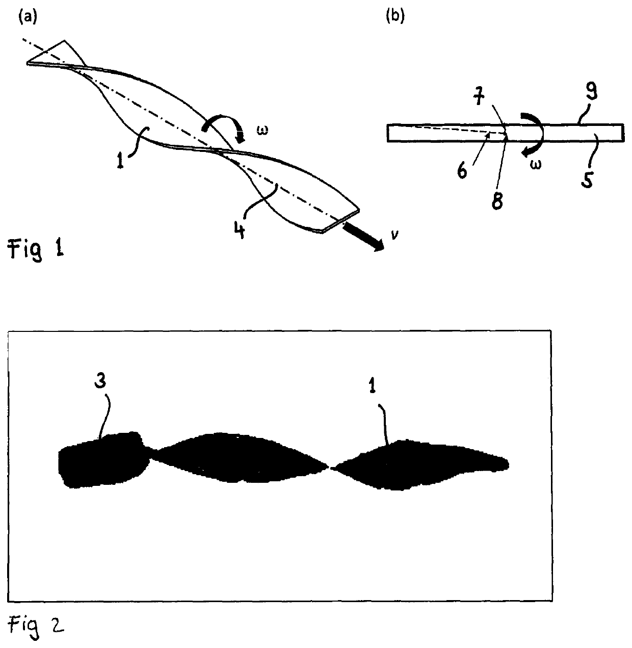
[0025]In a preferred embodiment of the invention, the aspect ratio of at least one cross section, preferably all cross sections, of the propeller, is / are 2 or more, more preferably 3 or more, more preferably 5 or more, more preferably 10 or more, more preferably 20 or more, more preferably 50 or more, more preferably 100 or more; the cross section(s) are related to the propeller's rotational axis or, alternatively, to the propeller's helical axis. This embodiment of the invention exploits the inventors' finding that a particularly high aspect ratio can entail a particularly strong propulsion. The cross section preferably is of a continuous shape.

[0026]Preferably, at least one cross section, more preferably every cross-section, of the propeller related to the propeller's rotational axis has a cross-sectional area that ...


PUM


Abstract

A method where a propeller is set into locomotion relative to a medium at least partially surrounding the propeller. An actuator induces a rotation of the propeller relative to the medium and about a rotational axis of the propeller, and the propeller converts its rotational movement into locomotion relative to the medium. The aspect ratio of at least one cross-section of the propeller is three or more. Also a helical or modifiedly helical propeller for converting rotational movement of the propeller into locomotion of the propeller relative to a medium at least partially surrounding the propeller, where the aspect ratio of at least one cross section of the propeller is three or more. And a method of producing a propeller, including the step of providing a plate extending along the helical axis, where the aspect ratio of at least one cross section of the plate is three or more.

Description

CROSS-REFERENCE TO RELATED APPLICATIONS[0001]This application is a national stage application under 35 U.S.C. § 371 of PCT Application No. PCT / EP2018 / 059331, filed Apr. 11, 2018, PROPELLER AND METHOD IN WHICH A PROPELLER IS SET INTO MOTION, published as WO 2018 / 189263 A1, which claims priority to and the benefit of European Patent Application No. 17166356.0, filed Apr. 12, 2017, which applications are incorporated herein by reference in their entirety.FIELD OF THE INVENTION[0002]The invention concerns a method in which a propeller is set into locomotion relative to a medium which at least partially surrounds the propeller, wherein an actuator induces a rotation of the propeller relative to the medium and about a rotational axis of the propeller, and wherein the propeller converts its rotational movement into locomotion of the propeller relative to the medium. It moreover concerns a helical or modifiedly helical propeller for converting rotational movement of the propeller into locom...

Claims


Application Information

Patent Timeline
Patent Type & Authority Patents(United States)
IPC IPC(8): B26D5/08B26D1/00A61B17/00A61B17/3207A61B34/00A61B34/30
CPCB26D5/086A61B17/00A61B17/320758B26D1/0006A61B34/73A61B2017/00345A61B2017/320775A61B2034/303B26D2001/0073A61B2017/00411
Inventor QIU, TIANFISCHER, PEER
Owner MAX PLANCK GESELLSCHAFT ZUR FOERDERUNG DER WISSENSCHAFTEN EV
Why Eureka
Try Eureka