
Apparatus and method for laminating fibers for direct manufacturing or preform

a technology of laminating fibers and fibers, applied in the field of apparatus and method for laminating fibers for direct manufacturing or preform, to achieve the effect of minimizing contamination, rapid laminating of reinforced fiber preform, and forming quickly

Active Publication Date: 2022-11-08
HIGH IN TECH CO LTD
View PDF18 Cites 0 Cited by
  • Summary
  • Abstract
  • Description
  • Claims
  • Application Information

AI Technical Summary

Benefits of technology

The apparatus and method for laminating fibers described in this patent allow for the rapid formation of a reinforced fiber preform by arranging multiple strands of reinforced fibers on a table. The reinforced fibers can be laminated by separately operating a robot for drawing and fixing the fibers, and adjusting the amount of drawing can control the shape of the preform. The reinforced fibers can also be cut simultaneously, and there is no need for a portion to apply thermoplastic resin or a heating part, reducing contamination and facilitating maintenance.

Problems solved by technology

By manually laminating the prepregs, the prepregs may be laminated in a desired shape, but the method has drawbacks in that as the prepregs become larger in size, a process time increases, and quality of products depends on competence of a manufacturer.
However, as described above, the method requires high costs, and a large autoclave for accommodating large prepregs.
However, the RTM method has a drawback in that the method requires much time for operation as the fibers should be fixed to the workpiece at corner regions of the workpiece by using an adhesive or a separate device.
Further, an adhesive applying part, a cooling part, a heating part, and a cutting part should be provided for every strand of fiber, such that a structure of an arrangement head (portion for laminating fibers on the workpiece) is complicated, and the arrangement head may be contaminated easily as the adhesive is repeatedly coagulated and melted in the arrangement head by the heating part.

Method used


Image

  • Apparatus and method for laminating fibers for direct manufacturing or preform
  • Apparatus and method for laminating fibers for direct manufacturing or preform
  • Apparatus and method for laminating fibers for direct manufacturing or preform

Examples


Embodiment Construction

[0039]The above and other aspects of the invention will become apparent from the following detailed description of preferred embodiments. Throughout the drawings and the detailed description, like reference numerals in the drawings denote like elements. Further, the relative size and depiction of these elements may be exaggerated for clarity, illustration, and convenience. In the following description, a detailed description of known functions and configurations incorporated herein will be omitted when it may obscure the subject matter of the present disclosure.

[0040]Hereinafter, an apparatus for laminating fibers for direct manufacturing of a preform according to the present disclosure will be described in detail with reference to the accompanying drawings.

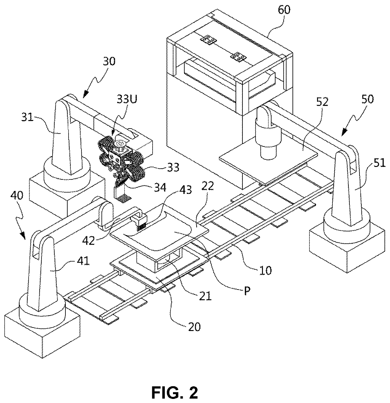
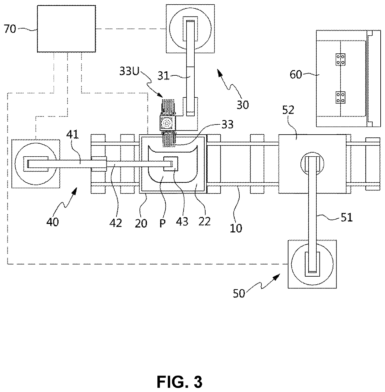
[0041]FIGS. 2 and 3 each are a schematic view and a plan view of an apparatus for laminating fibers for direct manufacturing of a preform according to an embodiment of the present disclosure.

[0042]As illustrated in FIGS. 2 and 3,...


PUM

PropertyMeasurementUnit
lengthaaaaaaaaaa
widthaaaaaaaaaa
timeaaaaaaaaaa

Abstract

An apparatus and method for laminating fibers for direct manufacturing of a preform, in which rows of fibers are drawn at the same time and are arranged in the form of a preform.The apparatus for laminating fibers for direct manufacturing of a preform according to an aspect of the present invention is an apparatus which supplies reinforced fibers to a table 22 and laminating the reinforced fibers thereon, so as to manufacture a fiber preform by laminating the reinforced fibers on the table 22, the apparatus including: a reinforced fiber supply robot 30 configured to supply a predetermined length of a plurality of reinforced fibers, on which a thermoplastic resin is coated; at least one or more edge fixing robots 40 configured to press and fix an end of the reinforced fibers drawn from the reinforced fiber supply robot 30 to the table 22 while the reinforced fibers are adhered as the thermoplastic resin is melted.Particularly, the reinforced fiber supply robot 30 includes: a plurality of reels 33, around which the reinforced fibers F coated with the thermoplastic resin are wound; a plurality of supply rollers 34 configured to transfer the reinforced fibers F, drawn from the plurality of reels, to the table 22 to supply the reinforced fibers thereto; a cutter configured to cut the reinforced fibers F, supplied through the plurality of supply rollers 34, into a predetermined length; and a compression roller 37 configured to press the end of the reinforced fibers F, cut by the cutter, to the table 22.

Description

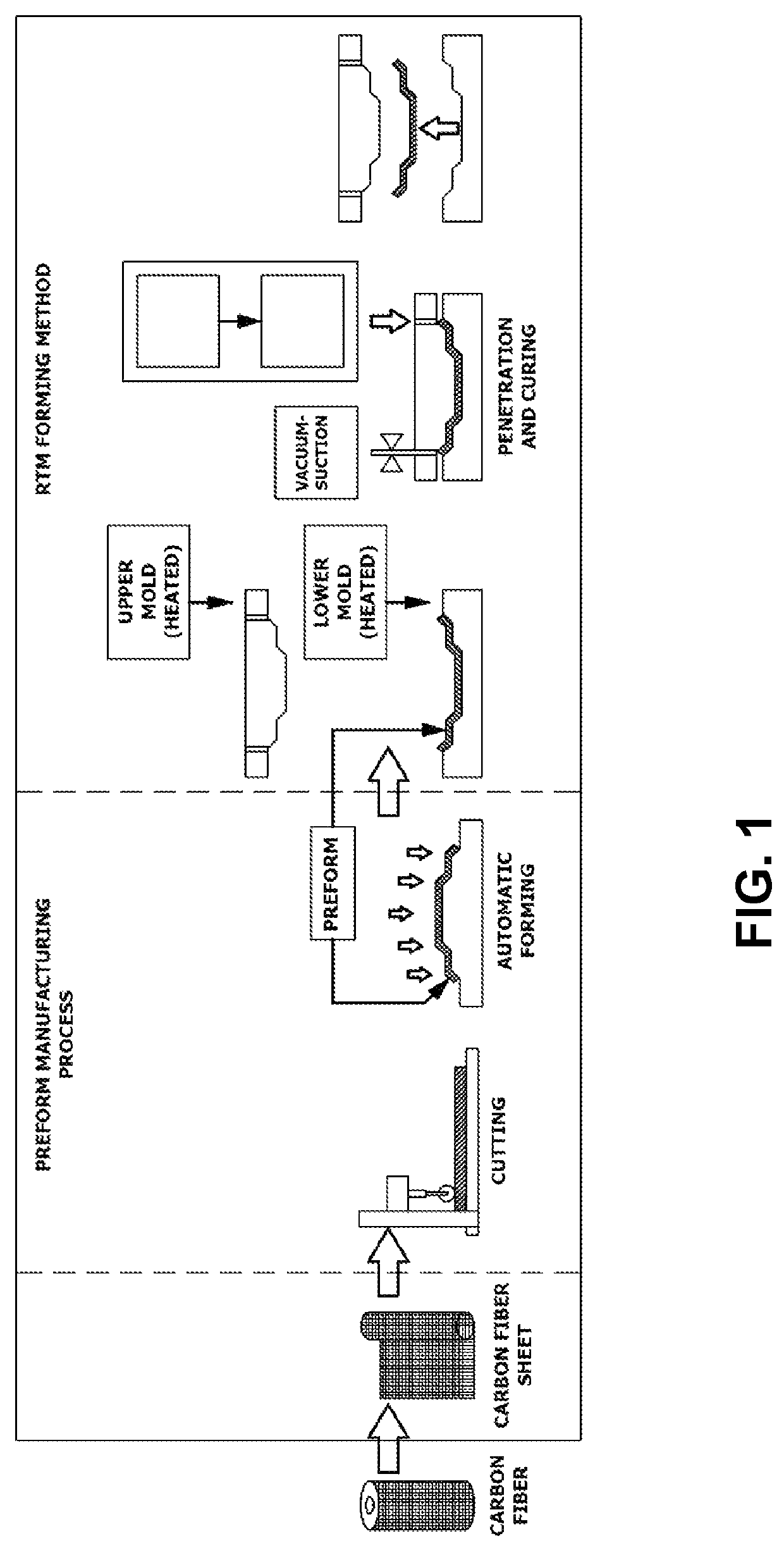
BACKGROUND1. Field[0001]The following description relates generally to an apparatus for laminating fibers for manufacturing a preform which is an intermediate product of fiber reinforced plastics, and more particularly to an apparatus and method for laminating fibers for direct manufacturing of a preform, in which rows of fibers are drawn at the same time and are arranged in the form of a preform.2. Description of the Related Art[0002]Fiber Reinforced Plastics (FRPs), which are a composite material composed of a resin and reinforced fibers such as glass fibers, carbon fibers, or nylon fibers, are lightweight and have excellent strength, and thus are widely used in various industries.[0003]Particularly, the FRPs, having mechanical properties of lightweight and excellent strength, are recently receiving attention as an automotive exterior material. Although a resin has excellent hardness but has low tensile strength, the resin may be reinforced with reinforced fibers, such that by usi...

Claims


Application Information

Patent Timeline
Patent Type & Authority Patents(United States)
IPC IPC(8): B29C70/06B29C70/38B29B11/12B29B11/16B29C70/48
CPCB29C70/382B29B11/12B29B11/16B29C70/06B29C70/48B29B11/06B29C70/38B29C70/545B29C70/543
Inventor KIM, HYUN DEUKYOON, SEON HEE
Owner HIGH IN TECH CO LTD
Learn More