
Exhaust gas aftertreatment system, and method for the exhaust gas aftertreatment of an internal combustion engine

Active Publication Date: 2022-11-08
VOLKSWAGEN AG
View PDF19 Cites 0 Cited by
  • Summary
  • Abstract
  • Description
  • Claims
  • Application Information

AI Technical Summary

Benefits of technology

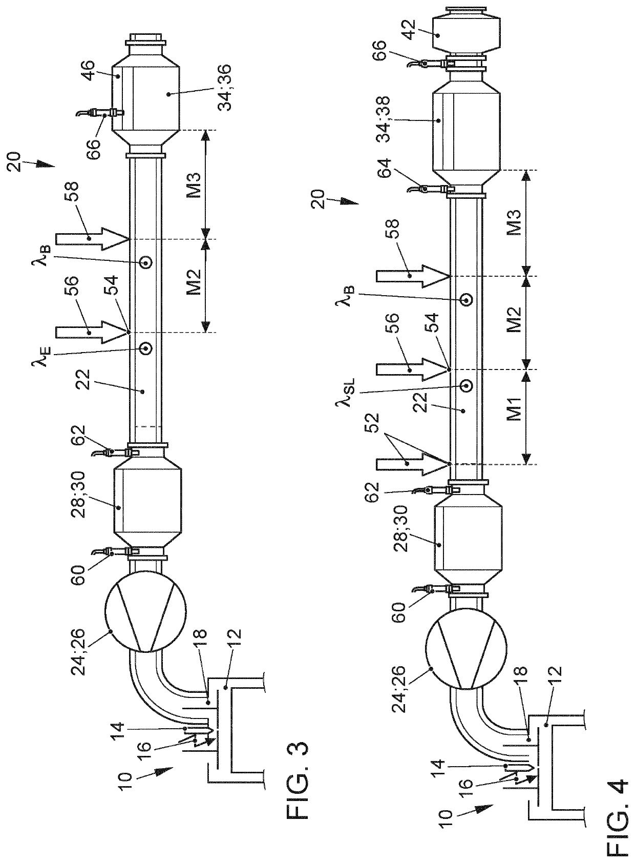
The invention is an exhaust gas aftertreatment system for an internal combustion engine that has a three-way function with a maximum inlet exhaust gas run length of 80 cm. The system includes a first catalytic converter close to the engine and a second catalytic converter downstream of the first converter. An exhaust gas burner is installed downstream of the first converter and upstream of the second converter, which introduces hot exhaust gas into the exhaust gas duct. A fuel injector is installed downstream of the inlet point of the exhaust gas burner and upstream of the second converter, which allows fuel to be metered into the exhaust gas duct before it reaches the second converter. This system increases heating output and allows for faster and more efficient conversion of gaseous pollutants in the exhaust gas stream from the engine compared to a system heated exclusively by the exhaust gas burner.

Problems solved by technology

The current exhaust gas legislation, which will become increasingly stringent in the future, places high demands on the tailpipe emissions of vehicles having internal combustion engines.
The disadvantage of the known solutions, however, is that large exhaust gas burners with high heating outputs are required for large, powerful internal combustion engines.
The output of the exhaust gas burner is limited by the maximum amount of fuel that can be converted based on the available installation space.
Thus, the burner output cannot be increased at will, which means that a further reduction of the heating time by the exhaust gas burner is not possible.

Method used


Image

  • Exhaust gas aftertreatment system, and method for the exhaust gas aftertreatment of an internal combustion engine
  • Exhaust gas aftertreatment system, and method for the exhaust gas aftertreatment of an internal combustion engine
  • Exhaust gas aftertreatment system, and method for the exhaust gas aftertreatment of an internal combustion engine

Examples


Embodiment Construction

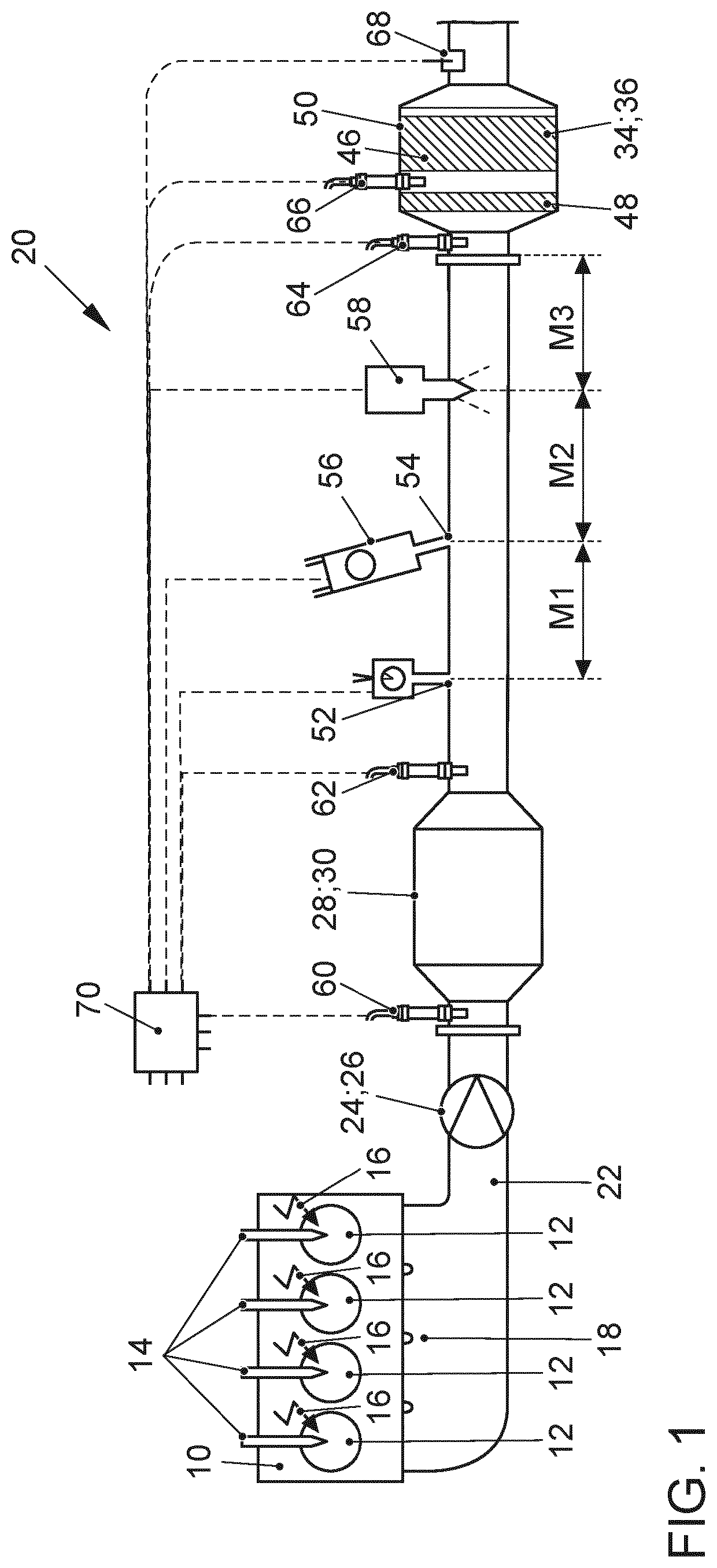
[0041]FIG. 1 schematically shows an internal combustion engine 10 which comprises a plurality of combustion chambers 12 and is connected via its outlet 18 to an exhaust system 20. The internal combustion engine 10 is designed as a direct-injection gasoline engine and has a fuel injector 14 and a spark plug at each combustion chamber 12 for igniting a combustible fuel-air mixture in the combustion chambers 12. The combustion chamber 12 is delimited by a piston which is arranged so as to be linearly displaceable in a cylinder bore of the internal combustion engine 10. The piston is connected via a connecting rod to a crankshaft of the internal combustion engine 10, which transmits the power of the internal combustion engine 10 to a transmission.

[0042]The exhaust system 20 comprises an exhaust gas duct 22 in which a turbine 26 of an exhaust gas turbocharger 24 is arranged in the flow direction of an exhaust gas from the internal combustion engine 10 through the exhaust gas duct 22, whi...


PUM


Abstract

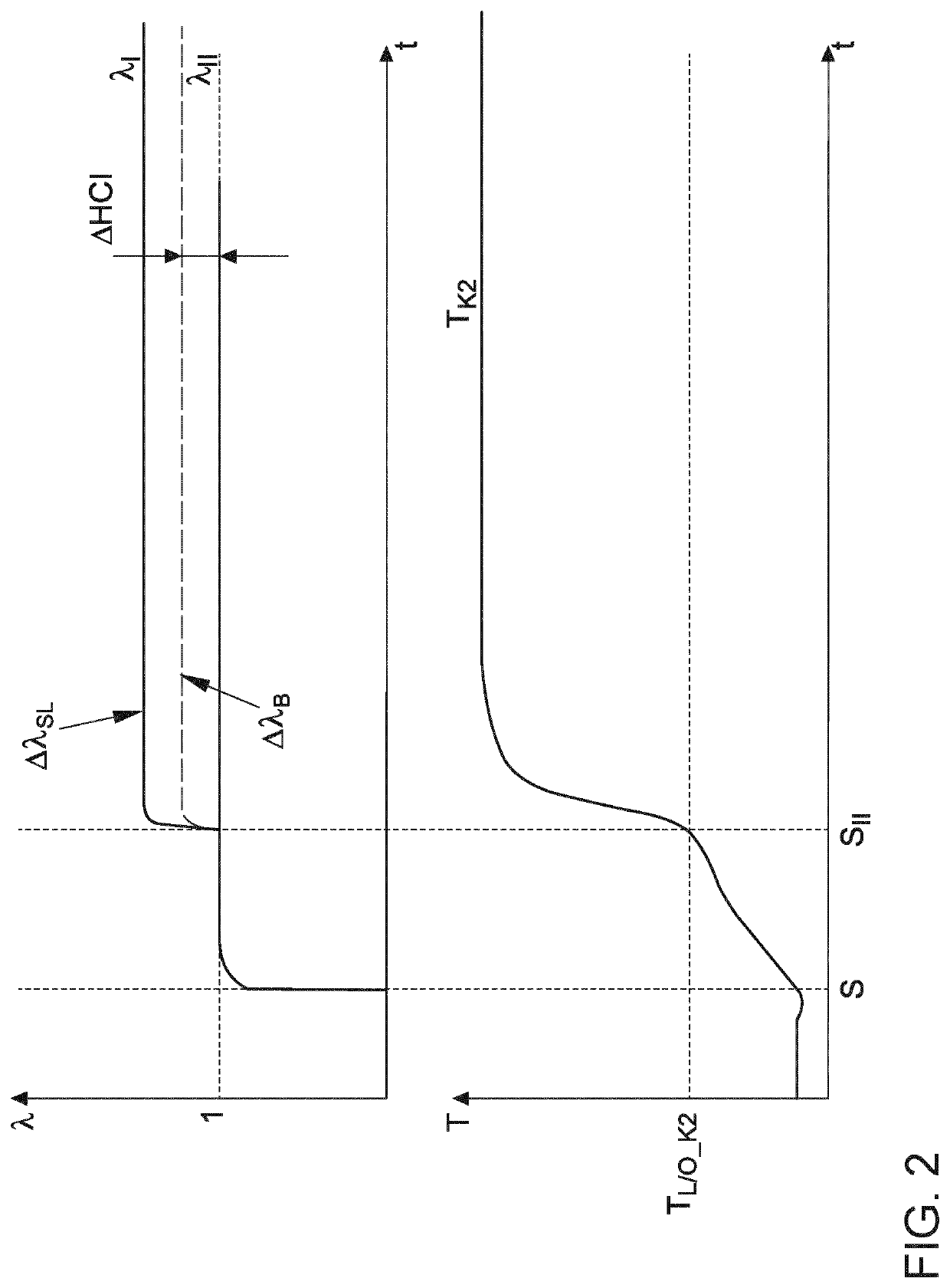
An exhaust gas aftertreatment system for an internal combustion engine, which comprises an exhaust system which can be connected to the outlet of an internal combustion engine. A catalytic converter close to the engine and a second catalytic converter arranged downstream of the catalytic converter in an underbody of a motor vehicle are provided in the flow direction of an exhaust gas from the internal combustion engine flowing through an exhaust gas duct of the exhaust system. An inlet point for secondary air, an exhaust gas burner, and a fuel injector for introducing fuel into the exhaust gas duct are arranged downstream of the catalytic converter close to the engine and upstream of the second catalytic converter. According to the invention, the exhaust gas burner is activated immediately after the internal combustion engine is started in order to heat the second catalytic converter to its light-off temperature. Once the second catalytic converter has reached its light-off temperature, secondary air and fuel are additionally introduced into the exhaust gas duct and are exothermically reacted on the second catalytic converter in order to support the heating of the second catalytic converter.

Description

CROSS-REFERENCE TO RELATED APPLICATIONS[0001]This application is a National Phase Application of PCT International Application No. PCT / EP2020 / 052937, International Filing Date Feb. 6, 2020, claiming priority of German Patent Application No. 10 2019 102 928.7, filed Feb. 6, 2019, which is hereby incorporated by reference.FIELD OF THE INVENTION[0002]The invention relates to an exhaust gas aftertreatment system and to a method for the exhaust gas aftertreatment of an internal combustion engine according to the preamble of the independent claims.BACKGROUND OF THE INVENTION[0003]The current exhaust gas legislation, which will become increasingly stringent in the future, places high demands on the tailpipe emissions of vehicles having internal combustion engines. The period immediately after a cold start of the internal combustion engine is of particular importance with regard to emissions, since in this phase the exhaust gas aftertreatment components should be heated to their operating t...

Claims


Application Information

Patent Timeline
Patent Type & Authority Patents(United States)
IPC IPC(8): F01N3/30F01N13/00F01N1/14F01N3/025F01N3/10F01N3/20
CPCF01N3/30F01N1/14F01N3/0253F01N3/101F01N3/2026F01N13/009F01N2240/14F01N2240/16F01N2550/14F01N2590/11F01N2610/03F01N2610/1453F01N3/021Y02T10/12
Inventor BOZALP, TOLGAPAUKNER, STEFANBARON VON CEUMERN-LINDENSTJERNA, FALK-CHRISTIANKAACK, MICHAEL
Owner VOLKSWAGEN AG
Learn More