
Eureka
For R&D, Eureka makes reading and utilizing patents & technical documents easy.
Eureka AIR
Designed for self-driven R&D workflows. Generate viable solutions, solve complex R&D challenges, empower your innovation with AI.

Eureka Materials
Designed for material experts only. Revolutionize your material R&D, from search, analyze, to developing new materials.

TechResearch
Generate reliable direction feasibility study reports for your R&D in just a few steps.

TechSeek
Discover and master advanced knowledge NOW. Basics, ideas, possibilities, all at once.

TechMind
As an expert in R&D Theories, TechMind can generates customized viable solutions instantly.

TechRisk
Analyze your overall solution with one click, know your potential R&D risks in advance.

TechMonitor
Get weekly tech updates, stay abreast of the latest tech innovations and key insights.
Robot
- Summary
- Abstract
- Description
- Claims
- Application Information
AI Technical Summary
Benefits of technology
Problems solved by technology
Method used
Image

Examples
first embodiment
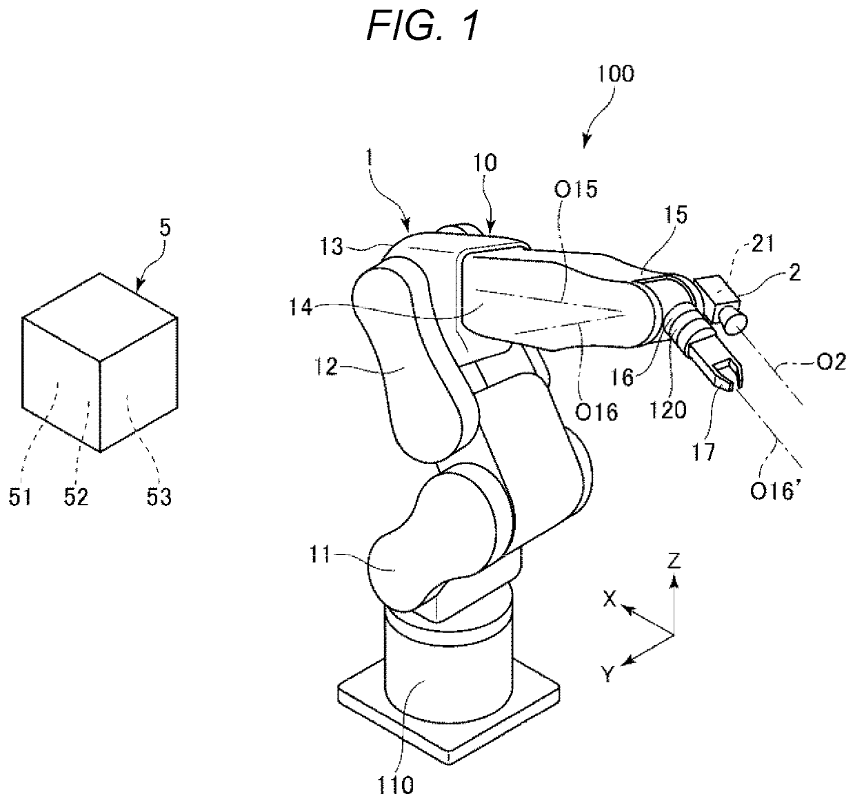
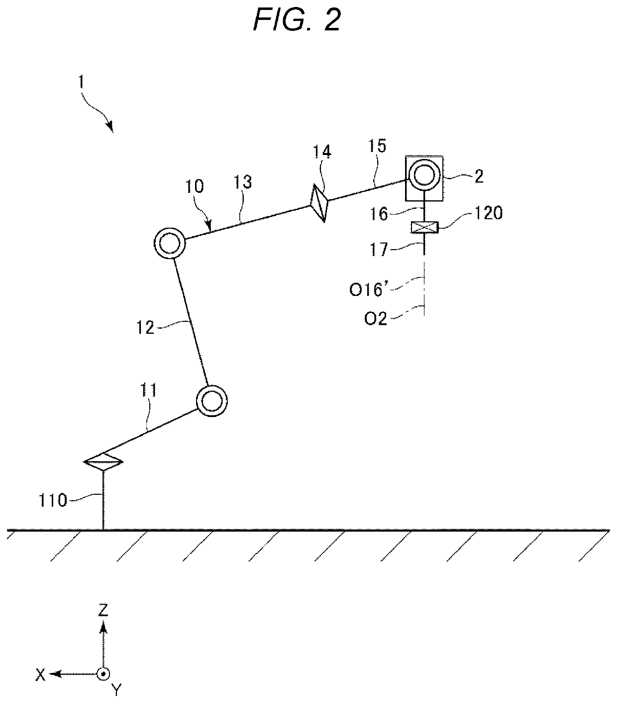
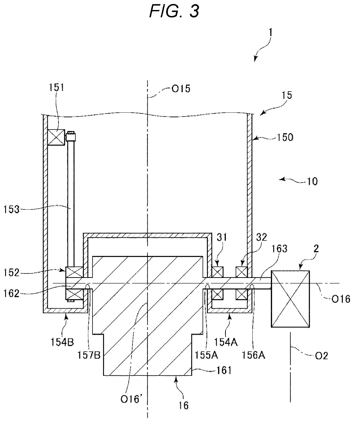
[0017]FIG. 1 is a diagram showing a robotic system provided with a robot according to a first embodiment. FIG. 2 is a schematic diagram of the robot shown in FIG. 1. FIG. 3 is a vertical cross-sectional view showing a coupling section between a first arm and a second arm.
[0018]In the present specification, the term “horizontal” includes the case of being tilted within ±10° with respect to a horizontal plane. Similarly, the term “vertical” includes the case of being tilted within ±10° with respect to a vertical plane. Further, the term “parallel” includes not only when two lines (including an axis) or planes are completely parallel to each other, but also when those are tilted within ±10° from each other. Further, the term “perpendicular” not only includes when two lines (including an axis) or planes cross each other at an angle of 90°, but also includes when those are tilted within ±10° with respect to 90°. Further, in the present specification, the word “couple” includes the case o...
second embodiment
[0063]Then, a second embodiment will be described.
[0064]FIG. 4 is a vertical cross-sectional view showing a coupling section between the first arm and the second arm in a robot according to the second embodiment.
[0065]The present embodiment is substantially the same as the first embodiment described above except mainly the point that the configuration of the coupling section between the first arm and the second arm is different. It should be noted that in the following description, the description will be presented with a focus on the difference from the first embodiment described above, and the description of substantially the same issues will be omitted.
[0066]As shown in FIG. 4, in the present embodiment, the support section 154B is provided with a through hole 158B as a hole disposed in the wall part on the opposite side to the arm 16 in addition to the through hole 157B as the hole. The through hole 157B and the through hole 158B are concentrically disposed centered on a straigh...
third embodiment
[0071]Then, a third embodiment will be described.
[0072]FIG. 5 is a vertical cross-sectional view showing a coupling section between the first arm and the second arm in a robot according to the third embodiment.
[0073]The present embodiment is substantially the same as the first embodiment described above except mainly the point that the configuration of the coupling section between the first arm and the second arm is different. It should be noted that in the following description, the description will be presented with a focus on the difference from the first embodiment described above, and the description of substantially the same issues will be omitted.
[0074]As shown in FIG. 5, in the present embodiment, the support section 154B shown in FIG. 3 is omitted, and there is provided a support section 154C corresponding to the support section 154A. The support section 154C has the through hole 155A and the through hole 156A. On the inner surface of the wall part provided with the through...
PUM
 Abstract
Description
Claims
Application Information
 - R&D Engineer
- R&D Manager
- IP Professional
- Industry Leading Data Capabilities
- Powerful AI technology
- Patent DNA Extraction
Browse by: Latest US Patents, China's latest patents, Technical Efficacy Thesaurus, Application Domain, Technology Topic, Popular Technical Reports.
© 2024 PatSnap. All rights reserved.Legal|Privacy policy|Modern Slavery Act Transparency Statement|Sitemap|About US| Contact US: help@patsnap.com