System and method for holding a workpiece in position for laser machining and/or welding thereof

Active Publication Date: 2022-11-15
LASER ENG APPL
View PDF6 Cites 0 Cited by
  • Summary
  • Abstract
  • Description
  • Claims
  • Application Information

AI Technical Summary

Benefits of technology

[0087]The advantage of the invention is that it is possible to machine or weld one or more rigid parts with a high precision. In fact, thanks to the absence of compression means for holding one or more rigid parts with respect to the electrically conductive support, it is possible to carry out very fine machining and/or welding with a weld seam which is well controlled spatially. Another advantage of the system and the method of the invention is that it is possible to machine and/or weld parts of any size without having to adjust compression means. This is particularly advantageous for small parts. Small parts have a maximum dimension of less than 5 cm, preferably less than 2 cm. Such parts would not be machinable by a roll-to-roll technique but are machinable by the system and method of the invention.
[0088]Preferably, the system of the invention further comprises a robotic arm for bringing said workpiece into contact with said electrically conductive support.
[0089]According to a

Problems solved by technology

When it is desired to machine or weld smaller parts, flexible substrates or flexible parts, it can become problematic to ensure that the parts are held with sufficient accuracy with respect to a machining device without damaging the parts by clamping the jaws.
The devices for holding and contacting parts to be machined devices of the prior art do not allow a good holding and/or contacting of parts to be machined while allowing accurate

Method used


Image

  • System and method for holding a workpiece in position for laser machining and/or welding thereof
  • System and method for holding a workpiece in position for laser machining and/or welding thereof
  • System and method for holding a workpiece in position for laser machining and/or welding thereof

Examples


Example

[0160]The drawings of the figures are not to scale. Generally, similar elements are denoted by similar references in the figures. The presence of reference numbers in the drawings cannot be regarded as limiting, even when such numbers are indicated in the claims.

DETAILED DESCRIPTION OF THE INVENTION

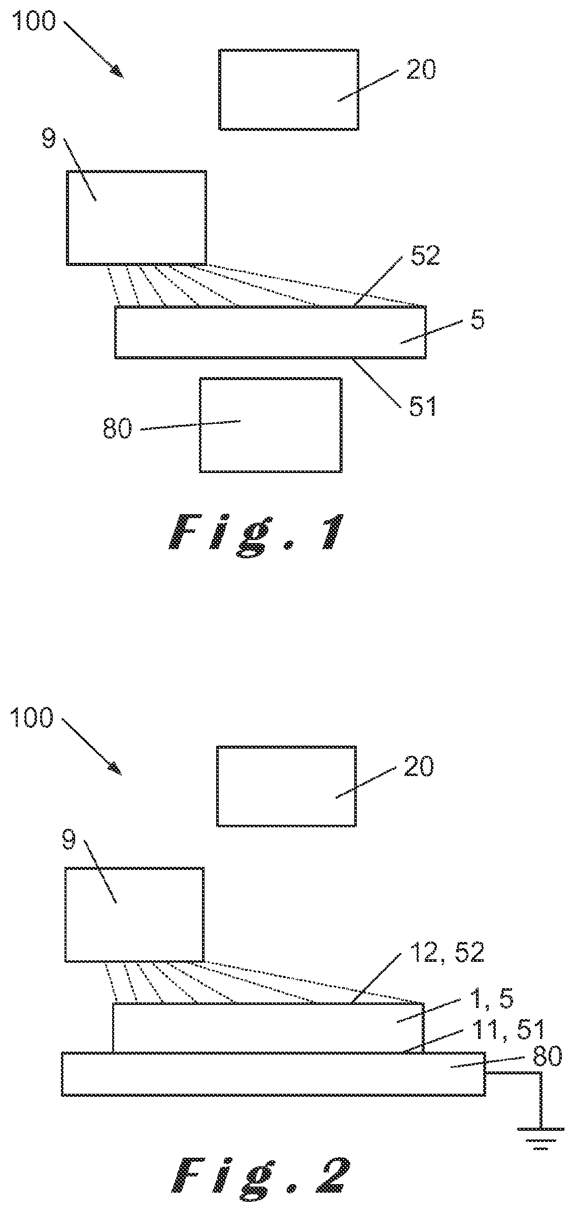
[0161]FIG. 1 shows an example of embodiment of the system 100 according to the invention where the workpiece 5 is positioned between the first electrostatic charge generating device 9 and an electrically conductive support 80, preferably metallic, grounded directly or indirectly. The electrically conductive support 80 is configured to be positioned close to the workpiece bottom surface 51. For example, the electrically conductive support 80 is positioned at a distance between 1 mm and 10 mm. For example the workpiece 5 is held at this distance by using support elements that can be electrically conductive or electrically insulating. This embodiment is particularly well suited to avoid dama...


PUM


Abstract

A system for holding a workpiece in position and exposing it to laser radiation, such that: the workpiece includes a bottom surface and a top surface that are electrically insulated from each other. The system includes an electrostatic charge generating device for generating electrostatic charges on the top surface; an electrically conductive support for forming, on the bottom surface, electrostatic charges of opposite sign to those generated on the top surface; and a laser device for machining or welding. The electrostatic charge generating device is arranged to be activated before or during the laser machining or welding, such that the workpiece is held in position relative to the electrically conductive support during the machining or welding thereof.

Description

TECHNICAL FIELD[0001]According to a first aspect, the invention relates to a system for holding a workpiece (or target, part) in position for its exposure to laser radiation. According to a second aspect, the invention relates to a method for holding a workpiece (or target) in position for its exposure to laser radiation.BACKGROUND[0002]The need to hold parts to allow them to be machined or welded is well known to the person skilled in the art. The holding and / or contacting of parts prior to machining or welding is very often achieved by means allowing one or more parts to be clamped between two clamping jaws mechanically connected to the machining or welding means.[0003]The machining or welding of rigid and massive parts is generally not a problem and clamping tools for such parts exist. When it is desired to machine or weld smaller parts, flexible substrates or flexible parts, it can become problematic to ensure that the parts are held with sufficient accuracy with respect to a ma...

Claims


Application Information

Patent Timeline
IPC IPC(8): B29C65/78B23K26/70B23K37/04B29C65/16B29C65/44B29C65/00
CPCB29C65/7852B23K26/702B23K37/0435B29C65/1616B29C65/1635B29C65/44B29C66/1122B29C66/45B29C66/5326B29C66/7352B29C66/742B29C66/7465B29C66/81262B29C66/81423B29C65/008B29C65/16B29C65/1674B29C65/8215B29C65/8246B29C65/8253B29C66/1222B29C66/1224B29C66/301B29C66/83413B29L2031/756B29C66/71B29C66/949B23K37/04B23K26/0624B23K26/082B29K2023/38
Inventor DÉCULTOT, MARCHENROTTIN, ANNEPATARS, JÉRÔMERAMOS DE CAMPOS, JOSE-ANTONIOKUPISIEWICZ, AXEL
Owner LASER ENG APPL
Why Eureka
Try Eureka