
High intensity discharge lamp, driving apparatus for high intensity discharge lamp, and high intensity discharge lamp system

a technology of high intensity discharge and driving apparatus, which is applied in the direction of electric variable regulation, cathode-ray/electron-beam tube circuit elements, instruments, etc., can solve the problems of reducing the life of the lamp, affecting the high intensity discharge lamp, and requiring higher cos

Inactive Publication Date: 2001-06-28
PANASONIC CORP
View PDF0 Cites 6 Cited by
  • Summary
  • Abstract
  • Description
  • Claims
  • Application Information

AI Technical Summary

Benefits of technology

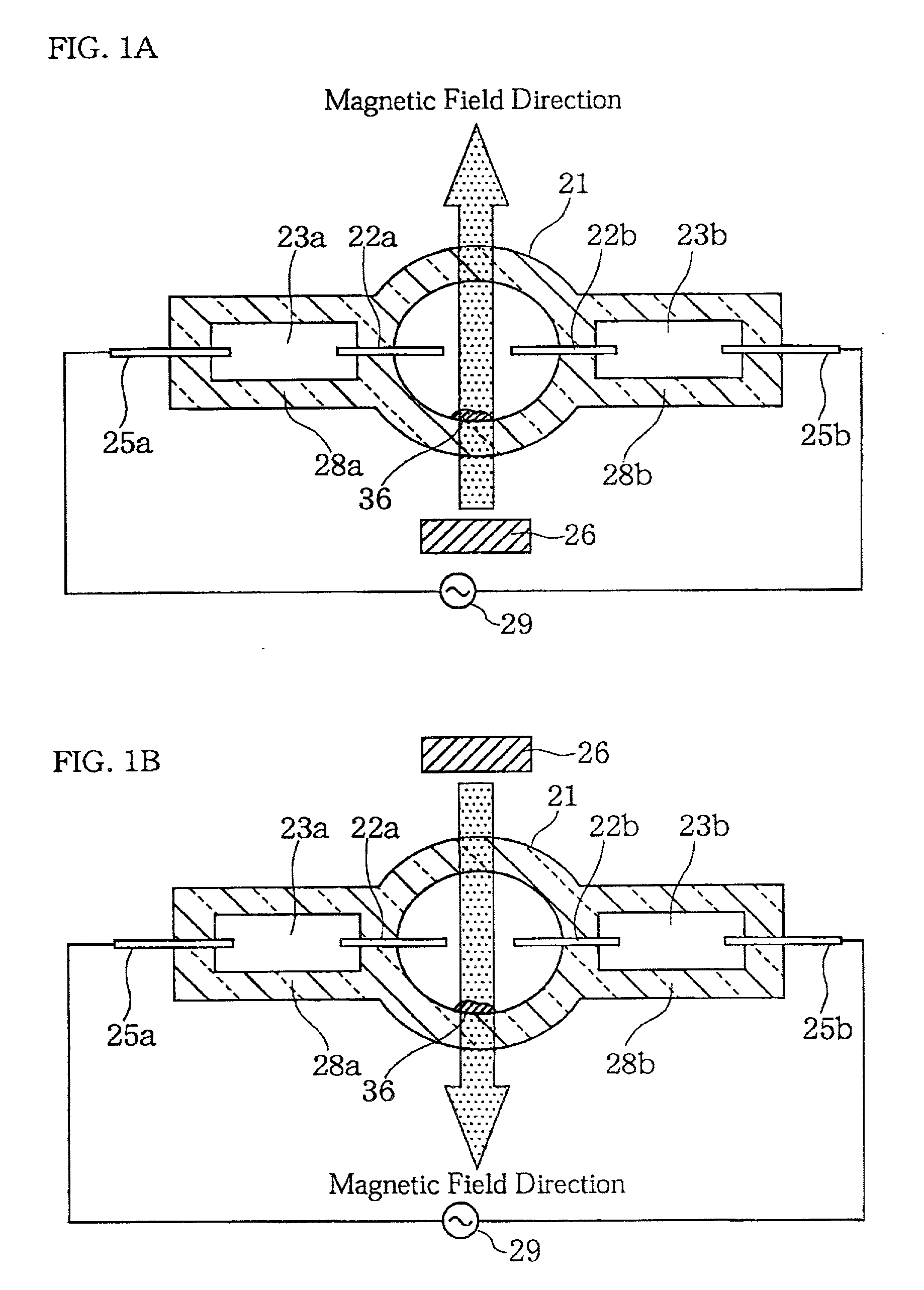
[0014] It is another object of the invention to provide, with a simple and low cost configuration, a high intensity discharge lamp in which at least one of an arc bend amount and an apparent arc width can be controlled.

Problems solved by technology

As a result, the temperature of the upper portion of the arc tube locally becomes high, which causes such problems that devitrification of the upper portion of the arc tube or deformation of the arc tube begins at a relatively early stage in lamp life and thus the lamp life reduces.
In addition, the high intensity discharge lamp requires a dedicated operating circuit, which incurs higher cost.
Unlike a halogen lamp having two filaments, it is difficult for the high intensity discharge lamp to attain both high beam and low beam with only one lamp.
Thus, this configuration also requires four sets of mechanism for adjusting the reflector and the light axis, which also incurs high manufacturing cost and limits the freedom in the vehicle designing.
However, according to a technique of controlling arc deflection by an electromagnet such as described above, an additional circuit for controlling the electric power supplied to the electromagnet is necessary, which incurs complicated device configurations and the increase in manufacturing cost.
It might be possible to control the arc deflection by varying a lamp current or a discharge electrode gap, rather than varying the electric power supplied to the electromagnet, but in practice, it would be very difficult to control variations in such factors.
When the width of the arc is reduced, the arc tends to become more susceptible to the convection current in the arc tube, resulting in a larger arc bend.

Method used


Image

  • High intensity discharge lamp, driving apparatus for high intensity discharge lamp, and high intensity discharge lamp system
  • High intensity discharge lamp, driving apparatus for high intensity discharge lamp, and high intensity discharge lamp system
  • High intensity discharge lamp, driving apparatus for high intensity discharge lamp, and high intensity discharge lamp system

Examples


example i-2

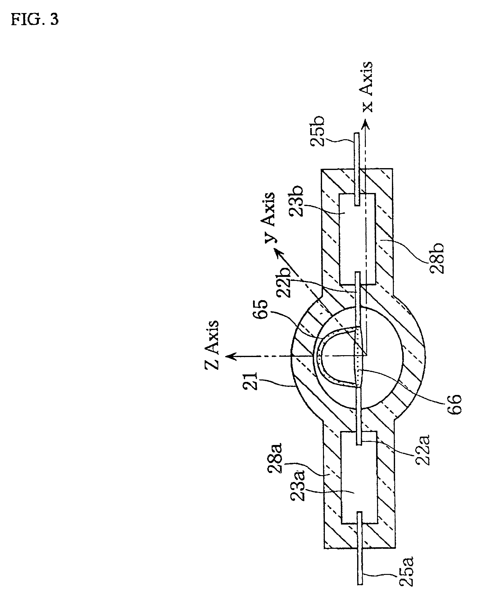
[0129] Now, Example I-2 of the present invention is discussed below. In the present example, there are shown several embodiments of the desirable positions of the magnetic field generating means to apply a magnetic field to a lamp.

[0130] FIG. 3 shows a schematic side view of a high intensity discharge lamp of Example I-2 according to the present invention. In FIG. 4, the reference numeral 21 denotes the arc tube described in Example I-1 above, and the detailed configuration of the lamp is identical to that of the high intensity discharge lamp shown in FIG. 1, except that the permanent magnet in FIG. 1 is not provided. The arc tube 21 is enclosed in an outer tube 24 made of transparent glass, and the outer tube 24 is fixed to a base 27. In the arc tube 21, a pair of electrodes (not shown) are provided and each of the pair of electrodes is connected to a lead (molybdenum lead) 25 via a metal foil (not shown). The reference numeral 30 denotes a magnetic material film coated on the oute...

embodiment ii

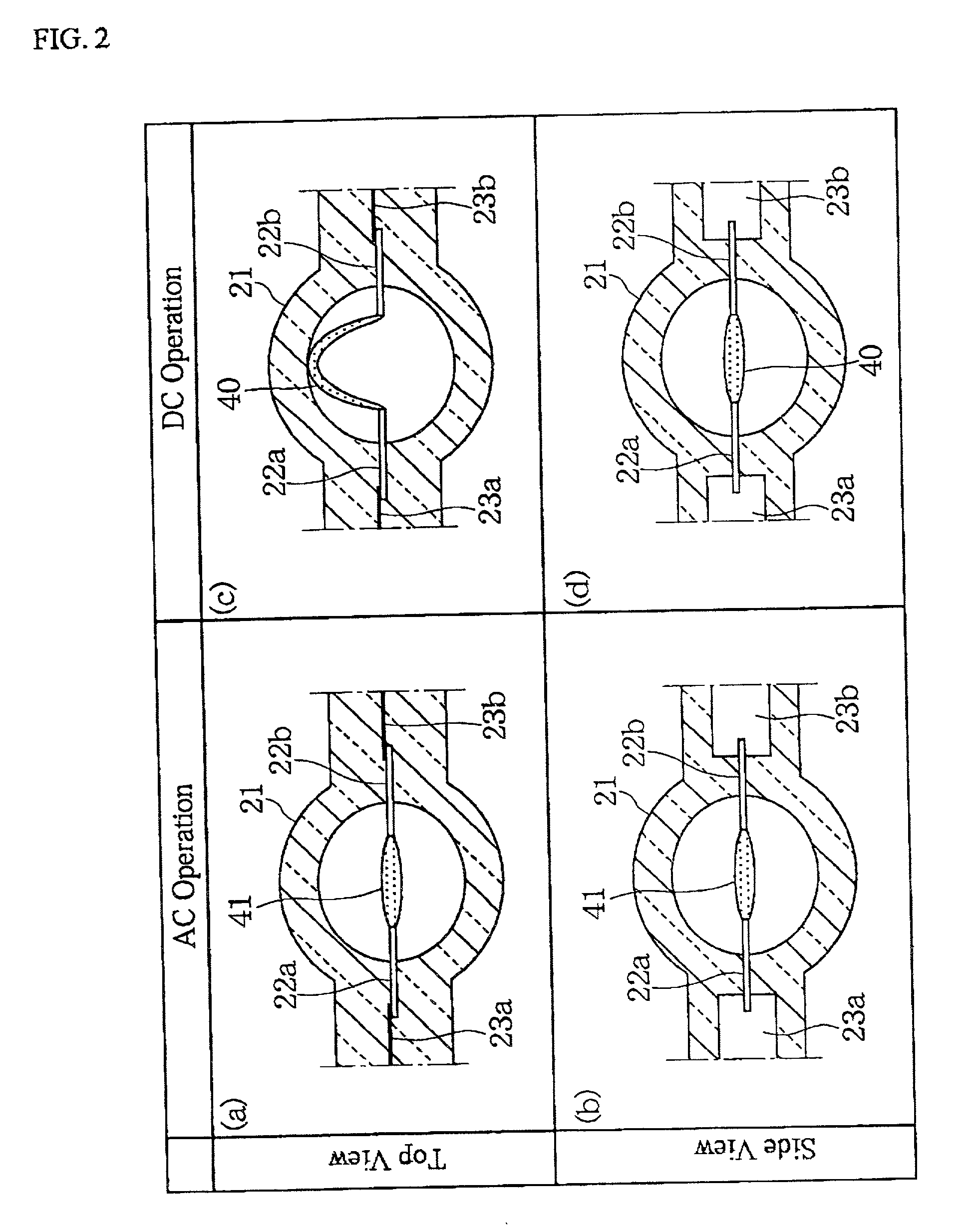
[0148] In Embodiment II, preferred embodiments of a high intensity discharge lamp having a magnetic field generating means for applying a magnetic field including a magnetic flux component perpendicular to a line connecting a pair of electrodes across the gap between a pair of electrodes provided inside the arc tube are discussed, and the lamp is configured such that alternating current is supplied between the pair or electrodes and a frequency of the alternating current is varied. Thereby, the arc bend amount can be controlled in a simple manner at low cost. Further, by varying the frequency of the alternating current with a frequency controlling means in the state where a magnetic field is applied in the same direction as that of the arc bend, an apparent arc width can be easily controlled. Specific examples thereof are discussed in the following Examples II-1, II-2, and II-3.

example ii-1

[0149] Now, with reference to the drawings, a preferred embodiment according to Embodiment II is detailed below.

[0150] FIG. 8 shows a schematic side view of a high intensity discharge lamp system 110 of Example II-1 according to the present invention. FIG. 9 shows a schematic cross sectional view illustrating the configuration of a high intensity discharge lamp 111 constituting the high intensity discharge lamp system 110. FIG. 16 illustrates an example in which the high intensity discharge lamp system of the present example is incorporated in an automobile.

[0151] As shown in FIG. 8, the high intensity discharge lamp system 110 of Example II-1 comprises a high intensity discharge lamp 111, a reflector 112, an operating circuit 113 and so forth.

[0152] The high intensity discharge lamp 111 is placed in the reflector 112 so that the line connecting a tip of one of the electrodes 122a and a tip of the other electrode 122b is horizontal (i.e., the lamp 111 is horizontally operated). The ...


PUM


Abstract

In a high intensity discharge lamp, at least one of an arc bend amount and an apparent width of arc is controlled by a simple configuration at low cost. A high intensity discharge lamp system 110 has a high intensity discharge lamp 111 and an operating circuit 113 for driving the high intensity discharge lamp 111. In the high intensity discharge lamp 111, a rare gas and a filling material 136 containing a metal halide as a light generating substance are enclosed in the arc tube 121 provided with a pair of electrodes 122a and 122b. The lamp system is disposed such that the line connecting the electrodes 122a and 122b is horizontal, and by applying a magnetic field having a vertical magnetic flux thereto and by varying the frequency of alternating current for driving the high intensity discharge lamp 111, at least one of an arc bend amount and an apparent width of arc can be easily controlled.

Description

[0001] (1) Field of the Invention[0002] The present invention relates to a high intensity discharge lamp for use in such apparatuses as general illumination apparatuses and vehicle headlamps that use the lamp mounted to a reflector, a driving apparatus for a high intensity discharge lamp, and a high intensity discharge lamp system employing the lamp and the driving apparatus.[0003] (2) Description of the Related Art[0004] In recent years, high intensity discharge lamps have been employed for projectors and vehicle headlamps in which the lamps are mounted to reflectors. Such discharge lamps exhibit high efficiency, low power consumption, and high intensity in comparison with halogen lamps, and therefore are expected to receive more widespread commercial acceptance.[0005] When a conventional high intensity discharge lamp is positioned in such a manner that the line connecting the pair of electrodes becomes horizontal, and operated by applying voltage across the pair of electrodes, (th...

Claims


Application Information

Patent Timeline
IPC IPC(8): H01J61/10H01J61/82
CPCH01J61/106H01J61/125H01J61/827
Inventor TAKAHASHI, KIYOSHIHORIUCHI, MAKOTOKANEKO, YURIKOKIRYU, HIDEAKITAKEDA, MAMORUMURASE, TAKAYUKIMINAMIHATA, RYO
Owner PANASONIC CORP
Learn More