Bagging and packaging machine capable of filling a proper quantity of inert gas into bags

a technology of inert gas and bagging machine, which is applied in the field of bagging and packaging machine, can solve the problems of increasing the amount of inert gas supplied per unitary time, increasing the cost of bagging products, and increasing the flow velocity of inert gas,

Inactive Publication Date: 2001-07-05
ISHIDA CO LTD
View PDF1 Cites 28 Cited by
  • Summary
  • Abstract
  • Description
  • Claims
  • Application Information

AI Technical Summary

Benefits of technology

[0019] According to the foregoing structure, the amount of the inert gas supplied by the gas supply means is at first set to a first flow rate in order to increase the gas replacement rate within the bag and, thereafter, set to a second flow rate lower than the first flow rate so that the amount of the inert gas consumed within the bag can be counterbalanced with, that is, equalized to the amount of the inert gas supplied into the bag. Accordingly, without the gas replacement rate within the bag being lowered, the amount of the inert gas supplied unnecessarily can advantageously suppressed to avoid an unnecessary increase of the amount of the gas used. Also, since the second flow rate is such as to avoid any undesirable blow-up of some of the articles within the bag, the supply of the inert gas at the second flow rate is effective to avoid any possible biting of the bag during a sealing operation of the bag with the articles filled therein, thereby minimizing production of unacceptable bagged products. In addition, since the first flow rate is chosen to be higher than the second flow rate, the inert gas can be filled at a high speed into the bag, thereby facilitating a bagging and packaging operation.
[0031] The use of the display means for providing the visual indication of the state of the inert gas being supplied from the gas supply means is particularly advantageous in that the attendant worker can visually grape the state of the inert gas being supplied such as the amount of the inert gas remaining in the gas supply means easily and, therefore, he or she knowing how much the inert gas remains in the gas supply means can launch a job of refilling the inert gas prior to the entire amount of the inert gas being consumed. Accordingly, the hour required to complete such a job can be reduced, making it possible for the bagging and packaging machine to perform the bagging and packaging operation efficiently.

Problems solved by technology

However, in the practice of the above discussed gas replacement method, although a relatively high rate of replacement with the inert gas can be secured as a large flow of the inert gas is supplied into each of the bags, it has been found that since the amount of the inert gas supplied from the gas supply unit is relatively large, the cost of making the bagged products tends to increase correspondingly.
In addition to the foregoing problem, another problem has been found in that with the above discussed gas replacement method, to maintain the rate of gas replacement at a relatively high level, the flow velocity of the inert gas has to be increased so that the amount of the inert gas supplied per unitary time can be increased.
However, increase of the gas flow velocity tends to result in that the inert gas is vigorously introduced into the bag and, consequently, some of items of the article to be bagged are blown upwardly within the bag and / or an introduction of the article towards the bottom of the bag is hampered.
In such case, when the upper seal is to be formed in the filled bag by means of the transverse sealing unit, some of items of the article which have been blown upwards within the bag or which have been retarded to reach the bottom of the bag are often "bitten" by the transverse sealing unit, resulting in an unacceptably defective bagged product.
However, other than the occasion that the prior art bagging and packaging machine is halted manually by the attendant worker when the bagging and packaging operation is desired to be interrupted, it often occurs that the bagging and packaging machine is halted or temporarily interrupted by some reason.
In such case, the gas supply unit incorporated in the bagging and packaging machine will continue supplying the inert gas regardless of the operating state (i.e., halted or interrupted) of the bagging and packaging machine, and therefore, the amount of the inert gas supplied, that is, the usage of the inert gas tends to be unnecessarily increased.
It has, however, been found that when and after the machine is resumed to the normal operating condition, a relatively long time is required for the flow rate of the inert gas being supplied to be stabilized at a predetermined value and, as a result, enhancement of the bagging and packaging operation at a high speed tends to be hampered and / or the gas replacement rate tends to be lowered.
By way of example, when in the event that the bagging and packaging machine is temporarily brought to a halt with the bagging and packaging operation consequently interrupted, the supply of the inert gas into the bag being filled with the article to be bagged is interrupted, the prior art bagging and packaging machine involves such a problem that the gas replacement rate within the bag decreases with passage of time subsequent to the interruption of the supply of the inert gas.

Method used


Image

  • Bagging and packaging machine capable of filling a proper quantity of inert gas into bags
  • Bagging and packaging machine capable of filling a proper quantity of inert gas into bags
  • Bagging and packaging machine capable of filling a proper quantity of inert gas into bags

Examples


Embodiment Construction

[0044] With reference to the accompanying drawings, the present invention will be described in detail in conjunction with a preferred embodiment thereof that is taken only for the purpose of illustration.

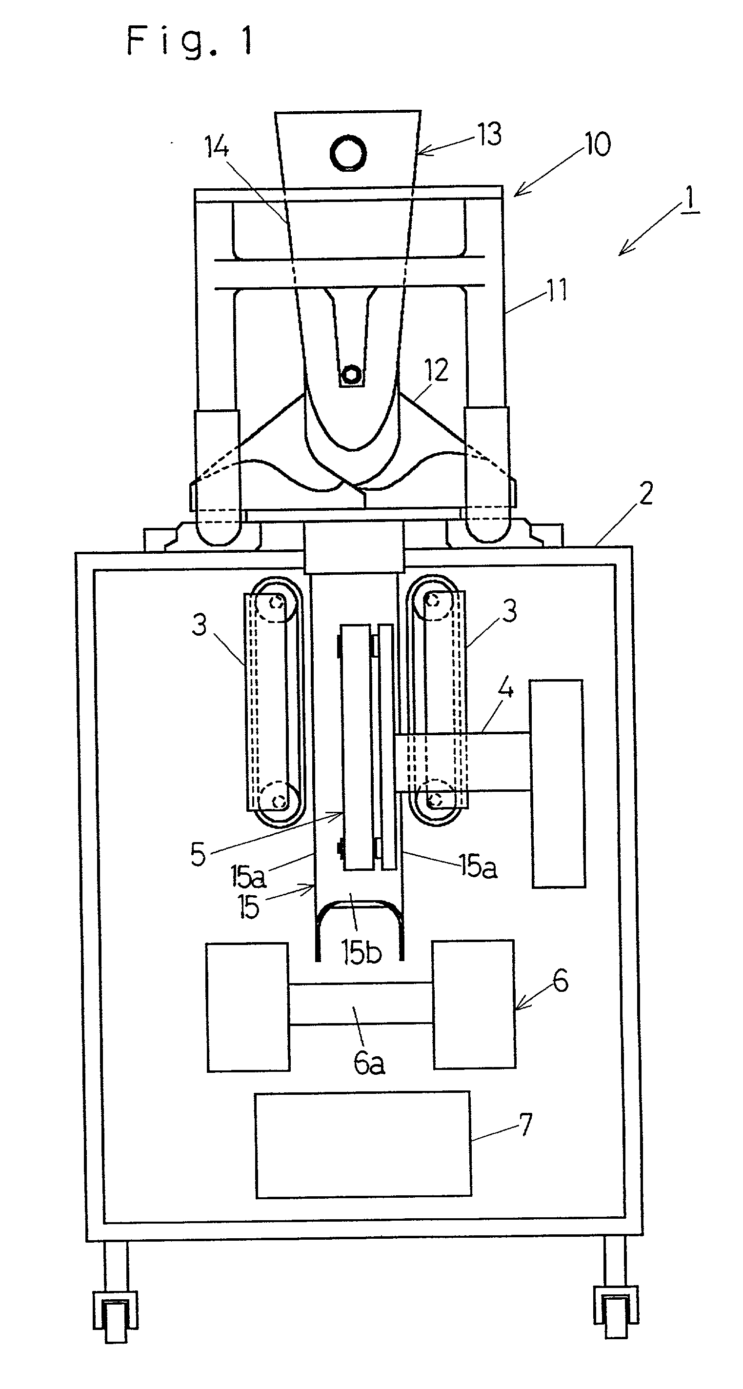
[0045] Referring first to FIG. 1, the bagging and packaging machine 1 according to the present invention includes a base framework 2, a roll support (not shown) mounted on a rear top portion of the base framework 2 for rotatably supporting a roll of packaging material and a bag former 10 mounted on a front top portion of the base framework 2.

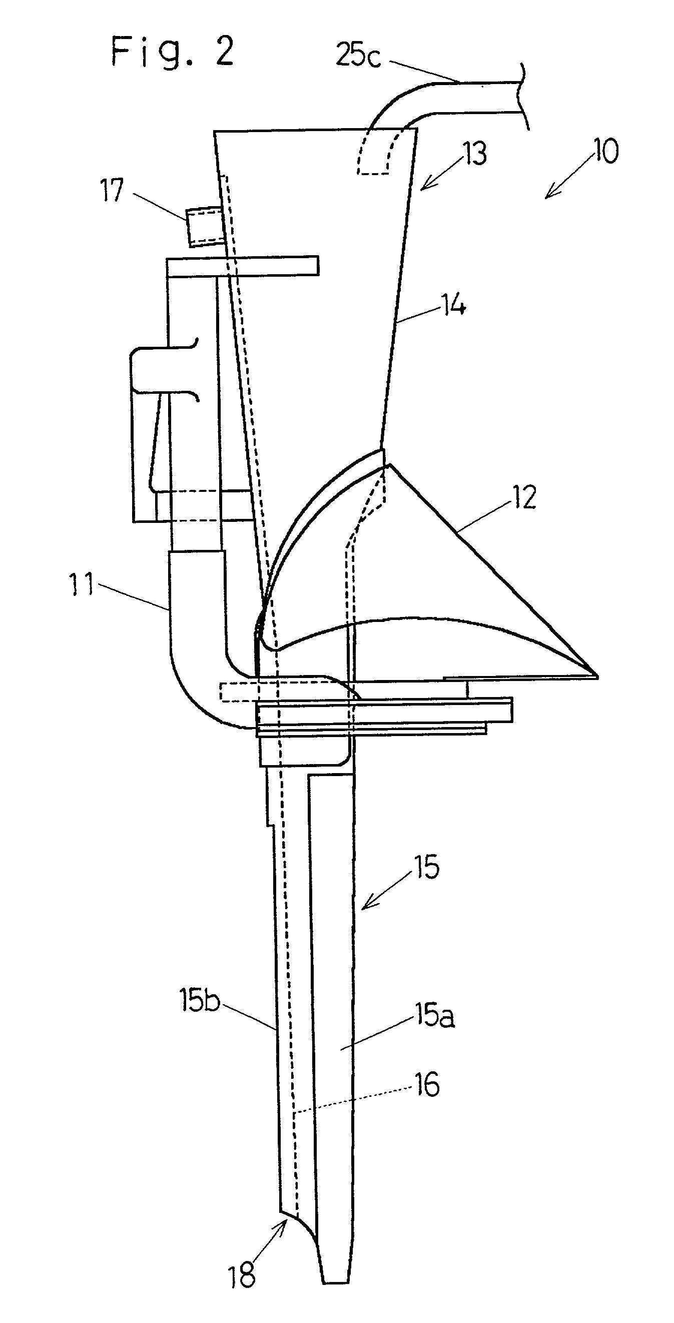
[0046] The bag former 10 of a unitary structure includes a frame 11 on which a sailor member 12 and a tube member 13 extending vertically through the sailor member 12 are mounted (See particularly FIG. 2). This bag former 10 is detachably mounted on a front upper surface of the base framework 2 and is so designed and so structured that as a strip of packaging material drawn outwardly from the roll of the packaging material can be guided downward...


PUM

PropertyMeasurementUnit
flow rateaaaaaaaaaa
length of timeaaaaaaaaaa
flow velocityaaaaaaaaaa

Abstract

A bagging and packaging machine for forming a bag from a strip of bag material and introducing an article into the bag includes a gas supply unit for supplying an inert gas into the bag to substitute for air contained in the bag and a gas supply control means for controlling supply of the inert gas by the gas supply means into the bag. The bagging and packaging machine is designed to allow the inert gas to be supplied under high pressure at a flow rate sufficient to increase the gas replacement rate in the bag when the machine is started, to be supplied under low pressure at a flow rate lower than the high pressure flow rate during a bagging and packaging operation subsequent to the start of the machine. Should the machine is temporarily brought to a halt, the length of time T passing from the timing at which the machine is temporarily brought to a halt is counted by a timer without the supply of the inert gas being interrupted, so that the supply of the inert gas can be interrupted at a timing the counted length of time exceeds a low pressure gas supply time T2. In this way, without the bag being bitten during bagging and / or the bagging and packaging speed being lowered, not only can the inert gas be sufficiently filled in the bag to achieve a high gas replacement rate, but the amount of the inert gas supplied can also be suppressed.

Description

[0001] 1. (Field of the Invention)[0002] The present invention generally relates to the art of packaging and, more particularly to a bagging and packaging machine for successively forming bags from a strip of bag material and subsequently packaging an article into each of the bags.[0003] 2. (Description of the Prior Art)[0004] In general, the bagging and packaging machine for successively producing bagged products by forming bags from a strip of bag material and subsequently packaging an article into each of the bag undergoes a process of forming the strip of bag material, supplied to a bag former, into a tubular form by means of the bag former by overlapping opposite longitudinal side edges with each other; fusion bonding, by means of a longitudinal sealing unit, the overlapped longitudinal side edges of the tubular strip of bag material in a direction longitudinally thereof at an outer surface of a front wall of an article introducing tube member forming a part of the bag former a...

Claims


Application Information

Patent Timeline
Patent Type & Authority Applications(United States)
IPC IPC(8): B65B31/04B65B57/18
CPCB65B9/20B65B9/2021B65B9/2028B65B31/04B65B31/045B65B57/18
Inventor KONDO, MASASHISATO, RYOICHI
Owner ISHIDA CO LTD
Why Eureka
Try Eureka