Braking pressure control apparatus capable of switching between two brake operating states using power-operated and manually operated pressure sources, respectively

a technology of braking pressure control and control apparatus, which is applied in the direction of braking systems, braking components, transportation and packaging, etc., can solve the problems of high drawback of the braking pressure control apparatus, and symptom indicating a high degree of probability of detecting an abnormality of the first hydraulic pressure sour

Inactive Publication Date: 2001-07-05
TOYOTA JIDOSHA KK
View PDF7 Cites 59 Cited by
  • Summary
  • Abstract
  • Description
  • Claims
  • Application Information

AI Technical Summary

Benefits of technology

[0009] A second object of this invention is to provide a braking pressure control apparatus which includes a first hydraulic system operable to operate a brake with a pressurized fluid delivered by a power-operated hydraulic pressure source and a second hydraulic system operable to operate the brake with a pressurized fluid having a pressure corresponding to the operating force of a brake operating member, and which apparatus permits more effective functioning of the first and second hydraulic systems.

Problems solved by technology

This braking pressure control apparatus suffers from a drawback which is caused upon switching of the operating state of the solenoid-operated valve device between the first and second states, for instance, an undesirable variation of the operating state of the brake operating member.
Further, the second hydraulic system is operated to operate the brake only while the first hydraulic system is abnormal.
Further, a symptom indicating a high degree of probability that the switching device switches the braking system from the first operating state to the second operating state is detected, for instance, when a predetermined condition for terminating the anti-lock braking pressure control is expected to be satisfied in the near future, and a symptom indicating a high degree of probability that a predetermined condition for terminating the vehicle turning stability control is expected to be satisfied in the near future.
For instance, an abnormality of the first hydraulic pressure source is detected when the pressure of the fluid pressurized by the pressurizing device of the first hydraulic pressure source is lower than a predetermined first lower limit.
In this case, a symptom indicating a high degree of probability that there exists an abnormality of the first hydraulic pressure source is detected when the pressure of the fluid pressurized by the first hydraulic pressure source is lower than a predetermined second lower limit higher than the first lower limit, and when the pressure is being lowered.
However, the average rate of increase of the fluid pressures in the first and second brake cylinder can be restricted.
In the second operating state, on the other hand, the flow of the pressurized fluid from the second hydraulic pressure source into the stroke simulator is not desirable, so that the simulator cut-off valve is placed in the closed state.
In this case, the pressurized fluid is delivered from the second hydraulic pressure source to the stroke simulator, resulting in an undesirable change of the operating stroke of the brake operating member.

Method used


Image

  • Braking pressure control apparatus capable of switching between two brake operating states using power-operated and manually operated pressure sources, respectively
  • Braking pressure control apparatus capable of switching between two brake operating states using power-operated and manually operated pressure sources, respectively
  • Braking pressure control apparatus capable of switching between two brake operating states using power-operated and manually operated pressure sources, respectively

Examples


second embodiment

[0287] FIG. 5 is a flow chart illustrating a control routine executed according to a control program stored in the ROM of a braking pressure control apparatus according to this invention, for controlling a simulator shut-off valve of a stroke simulator;

[0288] FIG. 6 is a view indicating fluid flows from a master cylinder and the stroke simulator toward a wheel brake cylinder when the simulator shut-off valve is controlled by the braking pressure control apparatus while the master cylinder pressure is higher than the wheel brake cylinder pressure;

[0289] FIG. 7 is a view indicating fluid flows from the wheel brake cylinder toward the master cylinder and stroke simulator when the simulator shut-off valve is controlled by the braking pressure control apparatus while the wheel brake cylinder pressure is higher than the master cylinder pressure;

third embodiment

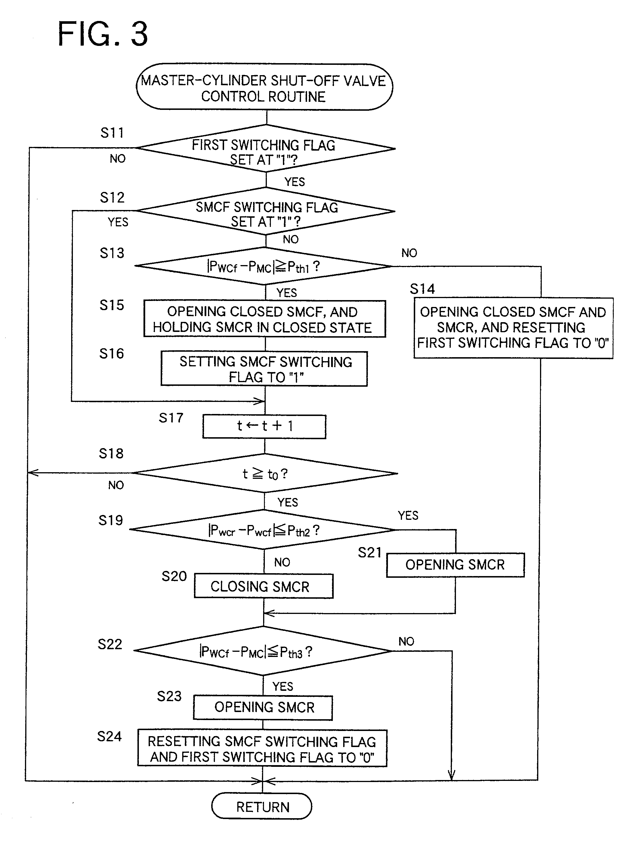
[0290] FIG. 8 is a flow chart illustrating a control routine executed according to a control program stored in the ROM according to this invention, for controlling the master-cylinder shut-off valves;

fourth embodiment

[0291] FIG. 9 is a flow chart illustrating a control routine executed according to a control program stored in the ROM of a braking pressure control apparatus according to this invention, for controlling the simulator shut-off valve and the master-cylinder shut-off valves while a brake pedal is not in operation;


PUM


Abstract

A braking pressure control apparatus including a first pressure source including a power-operated pressurizing device, a second pressure source operable by a manually operable brake operating member to pressurize a fluid to a pressure higher than a level corresponding to the operating force of the brake operating member, a switching device for selectively placing the braking system in a first state in which a brake cylinder is operated with the fluid pressurized by the first pressure source and a second state in which the brake cylinder is operated with the fluid pressurized by the second pressure source, and a change restricting device operable upon a switching between the first and second states, to restrict a change of the operating state of the brake operating member and a change of the brake cylinder pressure, which change take place due to the switching, or a switching control device for controlling the switching device on the basis of the running condition of a vehicle whose wheel is braked by the braking pressure.

Description

[0001] This application is based on Japanese Patent Applications Nos. 11-367991 and 11-367992 both filed Dec. 24, 1999, the contents of which are incorporated hereinto by reference.[0002] 1. Field of the Invention[0003] The present invention relates to a braking pressure control apparatus including two hydraulic systems for operating a hydraulically operated brake.[0004] 2. Discussion of Related Art[0005] JP-A-5-65060 discloses a braking pressure control apparatus including (1) a brake cylinder, (2) a power-operated hydraulic pressure source operable to pressurize a working fluid to a level corresponding to an operating force acting on a manually operable brake operating member, (3) a master cylinder operable with the operating force of the brake operating member to pressurize the fluid, and (4) a solenoid-operated valve device operable between a first state for fluid communication of the brake cylinder with the power-operated hydraulic pressure source, with the brake cylinder being...

Claims


Application Information

Patent Timeline
Patent Type & Authority Applications(United States)
IPC IPC(8): B60T8/36B60T8/40B60T8/44B60T8/94B60T13/68
CPCB60T8/367B60T8/4081B60T8/441B60T8/94B60T13/686B60T2270/602B60T2270/603B60T2270/613
Inventor KAGAWA, KAZUNORIMATSUKI, KIMIHIROMIYAZAKI, TETSUYAKAWAHATA, FUMIAKIOTOMO, AKIHIRONAKAMURA, EIJI
Owner TOYOTA JIDOSHA KK
Why Eureka
Try Eureka