Procedure and device for acoustically detecting microparticles

a technology of acoustically detecting and microparticles, applied in the direction of optical radiation measurement, mechanical vibration separation, instruments, etc., can solve the problems of inability to visually check the function of a dispenser, qualitatively or quantitatively, and the dispenser head must be repeatedly moved

Inactive Publication Date: 2001-07-12
MAX PLANCK GESELLSCHAFT ZUR FOERDERUNG DER WISSENSCHAFTEN EV
View PDF0 Cites 2 Cited by
  • Summary
  • Abstract
  • Description
  • Claims
  • Application Information

AI Technical Summary

Problems solved by technology

The microparticles released by a dispenser are generally so small that the function of a dispenser cannot be visually checked either qualitatively or quantitatively.
However, malfunctions are extremely disadvantageous, since samples or reactants might inadvertently not be made to interact on substrates in the desired manne

Method used


Image

  • Procedure and device for acoustically detecting microparticles
  • Procedure and device for acoustically detecting microparticles

Examples


first embodiment

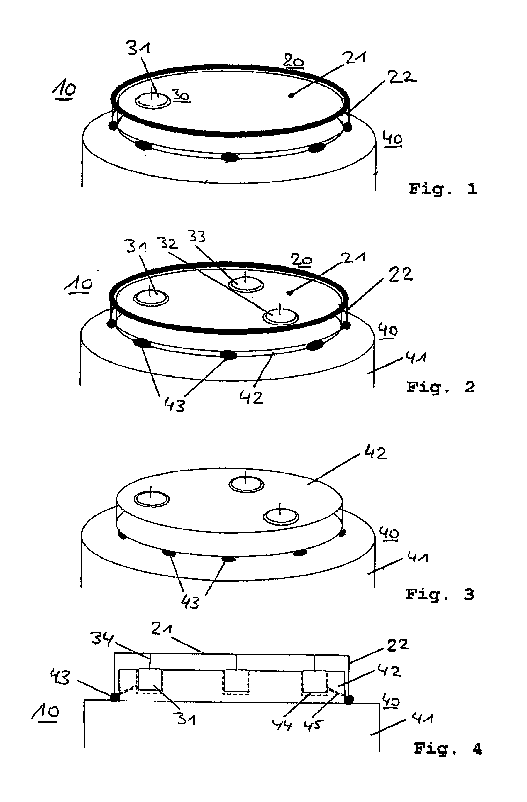
[0027] The first embodiment mentioned above (particle recording) of the detector 10 according to the invention is diagrammatically shown on FIG. 1. It comprises an oscillation target 20 with a flat sensor material 21, a sound converter 30 and a carrier 40. The flat sensor material is formed by a clamped-on sensor film. Use of the sensor film is not a compulsory feature of the invention. As an alternative, another layer or volume material can be provided to form a free surface as the target for the microparticles. The free surface is preferably larger than the typical lateral expansion of the dispenser on the dispenser head. However, the sensor film is preferred in this embodiment and the ones described below due to the relatively low running speeds of excited acoustic waves. Preferably, the sensor film (or sensor foil) has a thickness in the range below 100 .mu.m, preferably below 20 .mu.m. With decreasing film thickness the sound velocity (running speed of acoustic waves) decreases...

second embodiment

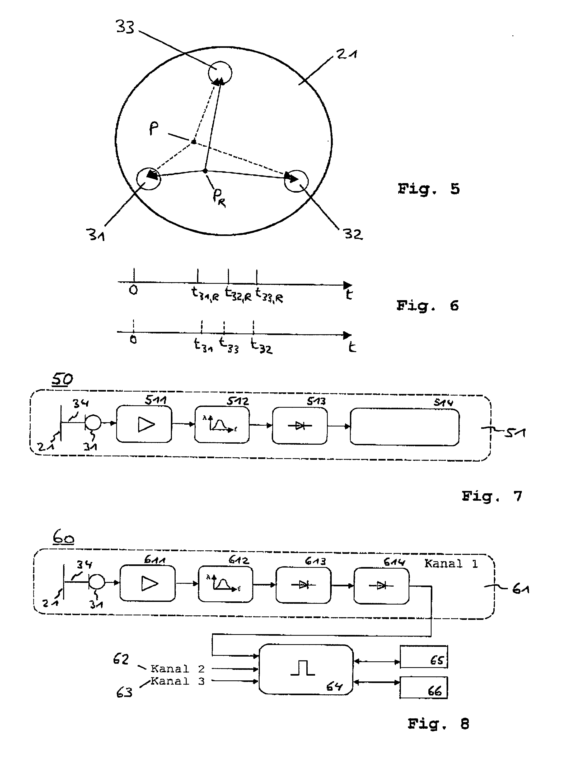
[0047] In addition, the sound converter 30 according to the aforementioned second embodiment can also consist of a combination of microphones and reflector elements at the edge of the sensor film 21, through which the corresponding paths from the impact positions to the microphone are defined. Finally, the design of the detector can also be modified relative to the used materials, shape and size of the sensor film. As an example, the sensor film can consist of a piezoelectric material. The thickness of the piezoelectric material preferably is in the range below 100 .mu.m, e.g. 20 .mu.m. The sound converters are formed by metallic layers being connected with the above data acquisition circuitry via electrical lines. The metallic layers are deposited in predetermined regions according to the positioning of the above microphones on one or both sides of the film. The deposition is preferably made by a lithographic procedure. This embodiment has the following particular advantages. The s...


PUM


Abstract

A procedure for detecting microparticles released by at least one dispenser, encompassing the following steps: (a) triggering the dispenser over an oscillation target (20) with a sensor material (21), so that at least one microparticle hits the sensor material (21) and excites an acoustic wave, (b) detecting the acoustic wave with at least one oscillation sensor (31) connected with the sensor material (21), which emits an electrical sensor signal when the acoustic wave arrives, and (c) evaluating the sensor signal to determine the impact of the microparticle. The procedure is aimed at detecting the impact and/or impact positions of microparticles on a target. A detector for executing the procedure is also described.

Description

[0001] The invention relates to a procedure for acoustically detecting microparticles, in particular for determining the appearance and / or positions of dispensed microparticles or for detecting the orientations of dispensers of a microparticle dispensing head, in particular for calibrating dispenser heads. The invention also relates to a procedure for executing such procedures, in particular to a detector for detecting the impact and / or impact position of microparticles released from a dispenser head.TECHNICAL BACKGROUND[0002] It is generally known to place the smallest amounts of solid and / or liquid substances on a substrate with a microdispenser in the form of drops or solid particles (hereinafter generally referred to as microparticles). The microdispenser is used to apply defined volumes on the substrate at predetermined positions. A microdispenser can have a dispenser head with several dispensers, for example to position various substances on the substrate.[0003] The microparti...

Claims


Application Information

Patent Timeline
IPC IPC(8): G01N29/04
CPCG01N29/046G01N2291/015G01N2291/02408
Inventor MULLER, MARTINGERMER, RUDOLFKALKUM, MARKUSEICKHOFF, HOLGER
Owner MAX PLANCK GESELLSCHAFT ZUR FOERDERUNG DER WISSENSCHAFTEN EV
Why Eureka
Try Eureka