
High reliability pointing device for graphical user interface navigation

Inactive Publication Date: 2001-08-09
IBM CORP
View PDF0 Cites 2 Cited by
  • Summary
  • Abstract
  • Description
  • Claims
  • Application Information

AI Technical Summary

Benefits of technology

[0013] It is another object of the present invention to provide such a pointing device that has fewer moving parts and is more difficult to damage or disable.
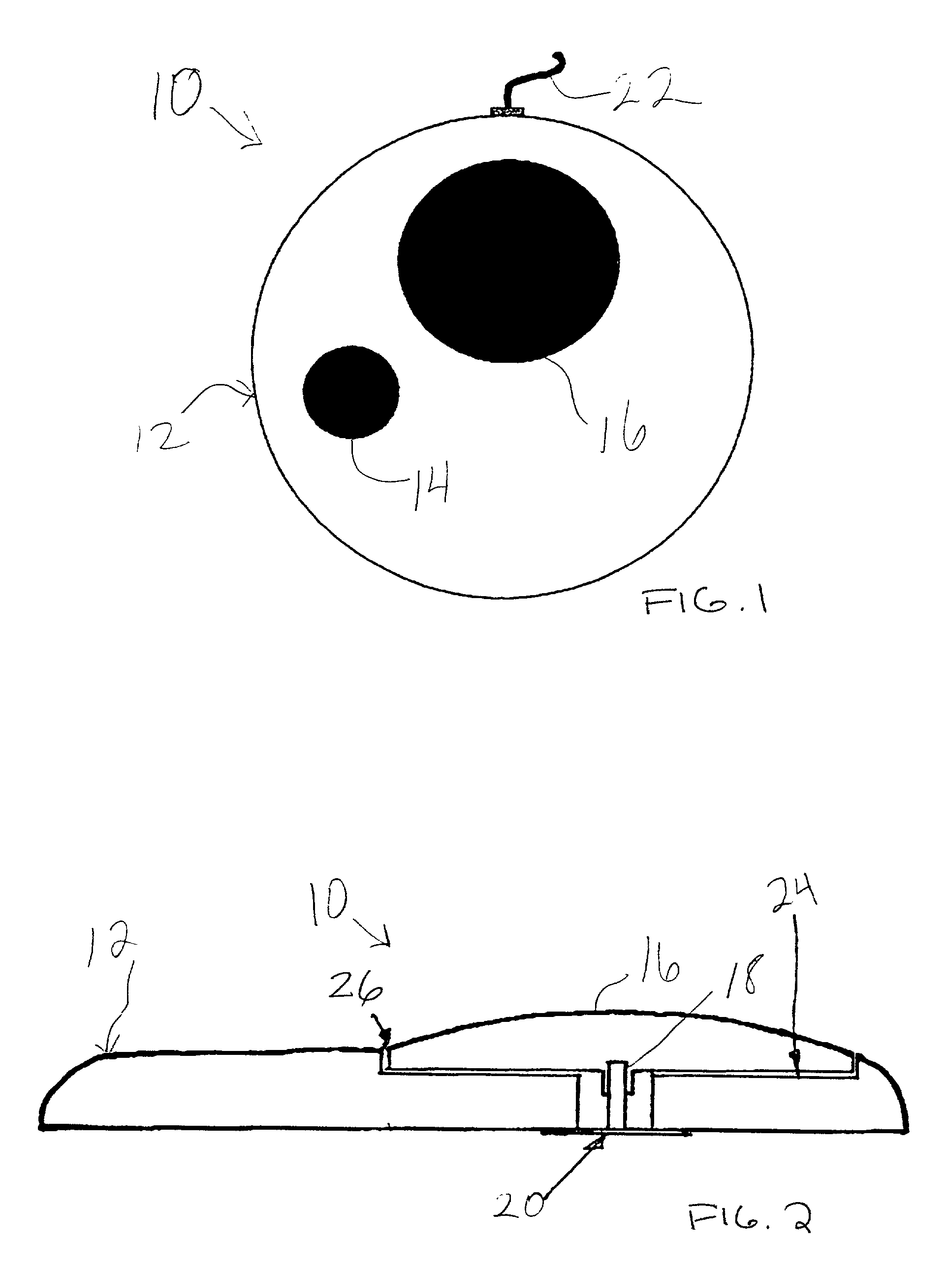
[0015] The foregoing objects are achieved in a pointing device for registering a desired direction of movement of a graphical pointer on a display of a computer system, generally comprising a base, a vertical member secured to the base, a pad mounted on the member such that manual pressure at a point near a periphery of said pad causes deflection of the member in a direction toward the pressure point, and appropriate electronics for translating a pitch angle of the vertical member into electrical signals, which can then be conveyed to a controller of the computer system. At least one actuation button is mounted to the base to allow selection of objects on the display, or other mouse operations. The pad is preferably located within a recessed portion of the base, and deflection of the pad is limited by an adjacent recessed surface and a rim of the base. The pointing device of the present invention has essentially no moving parts, and so is highly reliable and resistant to damage and is well suited to environments where space is a premium.

Problems solved by technology

Most pointing devices for computers are not well suited for use in high volume environments such as schools, libraries, airports, daycare centers, etc.
They are subject to damage from accumulated debris, spills, and deliberate abuse (e.g., removal of the ball from a mouse, rendering the device unusable which often further disables the computer as a practical matter).
In one, the ball itself may be removed from the base, which is unacceptable not only because the ball may become lost or unusable, but also because it can become a dangerous projectile in the hands of a child.
In the other implementation, the ball cannot be removed from the base, but this makes cleaning the ball and interior components (the rollers that are connected to the transducers) inconvenient or impossible.
The IBM Trackpoint device has had a further problem in that it is not particularly suitable for many users, including seniors, those disabled, and young children, as it requires too much dexterity.
Also, the pointing stick of these devices usually has a small rubber (gripping) tip on its ends, and removal of the tip is again a problem (and presents a choking hazard for very small children).

Method used


Image

  • High reliability pointing device for graphical user interface navigation

Examples


Embodiment Construction

[0020] With reference now to the figures, and in particular with reference to FIG. 1, there is depicted one embodiment 10 of the pointer device of the present invention. Pointer device 10 is adapted for use with a computer system having a visual display, wherein the computer system executes an operating system or application program that provides a graphical pointer on the visual display. The details of the remainder of the computer system are omitted here since they are generally conventional and well-known. However, while the present invention can be used with a computer system whose other components are conventional, the present invention could also be applied to computer systems that are not necessarily conventional, i.e., they could include new hardware components or have a novel interconnection architecture for existing components. Therefore, those skilled in the art will appreciate that the present invention is not limited in application to any specific computer system.

[0021]...


PUM


Abstract

A pointing device for a computer system, comprising a base, a joystick secured to the base, and a circular pad mounted centrally on the joystick such that manual pressure at a point near a periphery of the pad causes deflection of the joystick in a direction toward the pressure point. Appropriate electronics are used for translating a pitch angle of the joystick into electrical signals, which can then be conveyed to a controller of the computer system. An actuation button is mounted to the base to allow selection of objects on the display, or other mouse operations. The pad is located within a recessed portion of the base, and deflection of the pad is limited by an adjacent recessed surface and a rim of the base.

Description

[0001] 1. Field of the Invention[0002] The present invention generally relates to computer systems, and more particularly to pointing devices for visual displays, such as those commonly referred to as a "mouse." The present invention is directed to an improved hardware design for such a graphical pointing device.[0003] 2. Description of Related Art[0004] A computer system includes many components, such as the central processing unit (CPU, or processor), temporary memory for storing program instructions (like random access memory, or RAM), a permanent storage device (such as a hard disk), and a variety of user-interface devices, such as a video display, a keyboard, and a pointing device which controls the movement of a graphical pointer or cursor on the display. The graphical pointer typically takes the form of an arrow having a hot spot that specifies the exact location of the pointer when the user presses one or more buttons of the pointing device. The graphical pointer is used to ...

Claims


Application Information

Patent Timeline
IPC IPC(8): G06F3/033
CPCG06F3/0338
Inventor HOPPER, GREGORY
Owner IBM CORP
Learn More