Sheet detection system

Inactive Publication Date: 2001-08-16
L3 COMMUNICATIONS SECURITY & DETECTION SYSTEMS CORPORATION
View PDF0 Cites 17 Cited by
  • Summary
  • Abstract
  • Description
  • Claims
  • Application Information

AI Technical Summary

Benefits of technology

0005] It is therefore an object of this invention to provide an i

Problems solved by technology

Since a single dimension X-ray system can only produce a two dimensional or areal density, that is, weight per unit area related to the projected area of an object, it is not entirely reliable: the projected density is a composite of all densities in the line of the X-ray beam and one material can mask another.
Bu

Method used


Image

  • Sheet detection system
  • Sheet detection system
  • Sheet detection system

Examples


Embodiment Construction

[0012] Other objects, features and advantages will occur to those skilled in the art from the following description of a preferred embodiment and the accompanying drawings, in which:

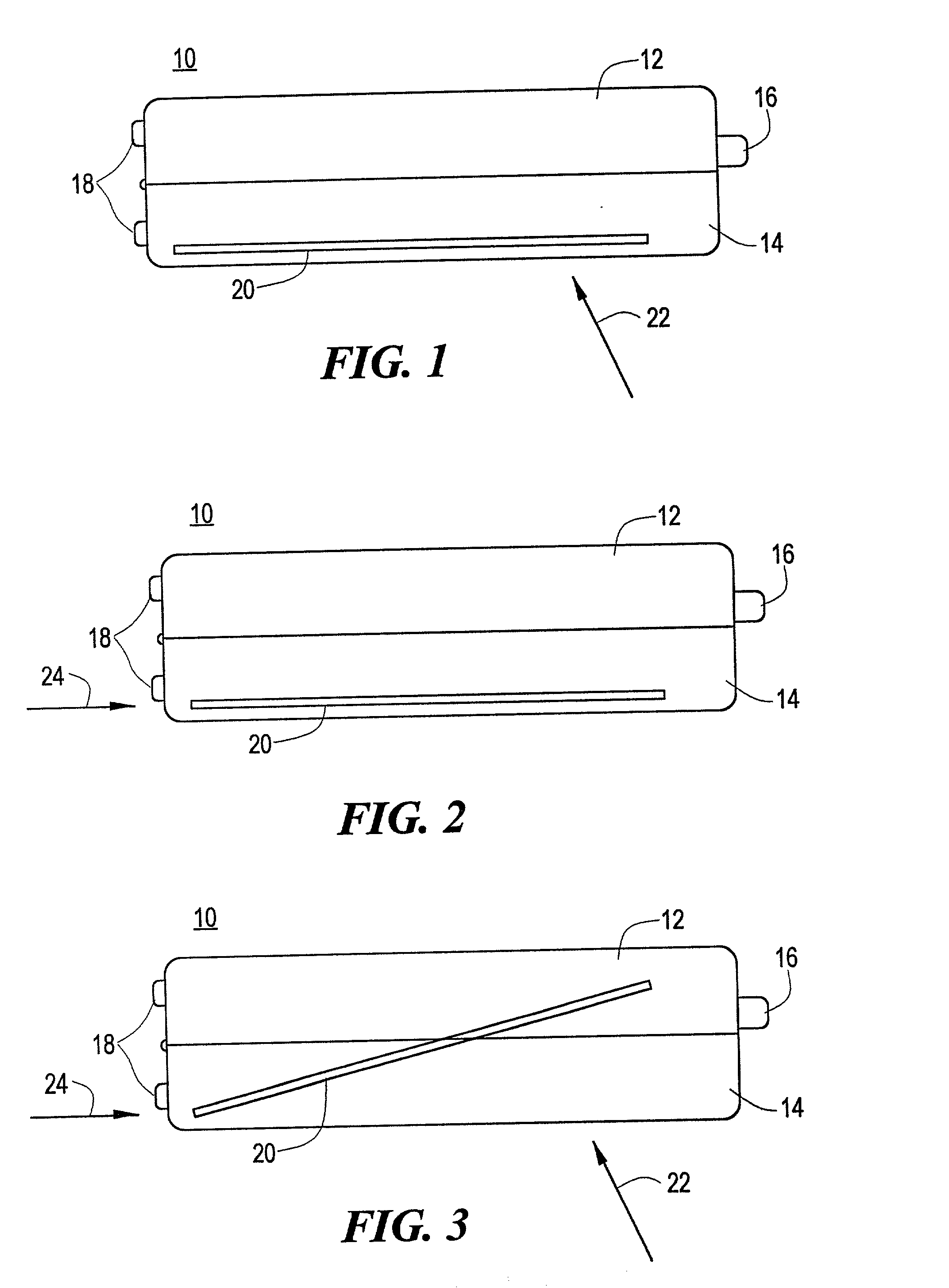
[0013] FIG. 1 is a schematic side elevational view of a suitcase harboring a sheet of material being imaged by an X-ray scan generally perpendicular to the sheet, wherein detection is unlikely;

[0014] FIG. 2 is a view similar to FIG. 1 with the sheet being imaged end-on by the X-ray scan where detection is most likely;

[0015] FIG. 3 is a view similar to FIGS. 1 and 2 with the sheet being imaged at an angle to two differently oriented X-ray scans wherein detection is unlikely;

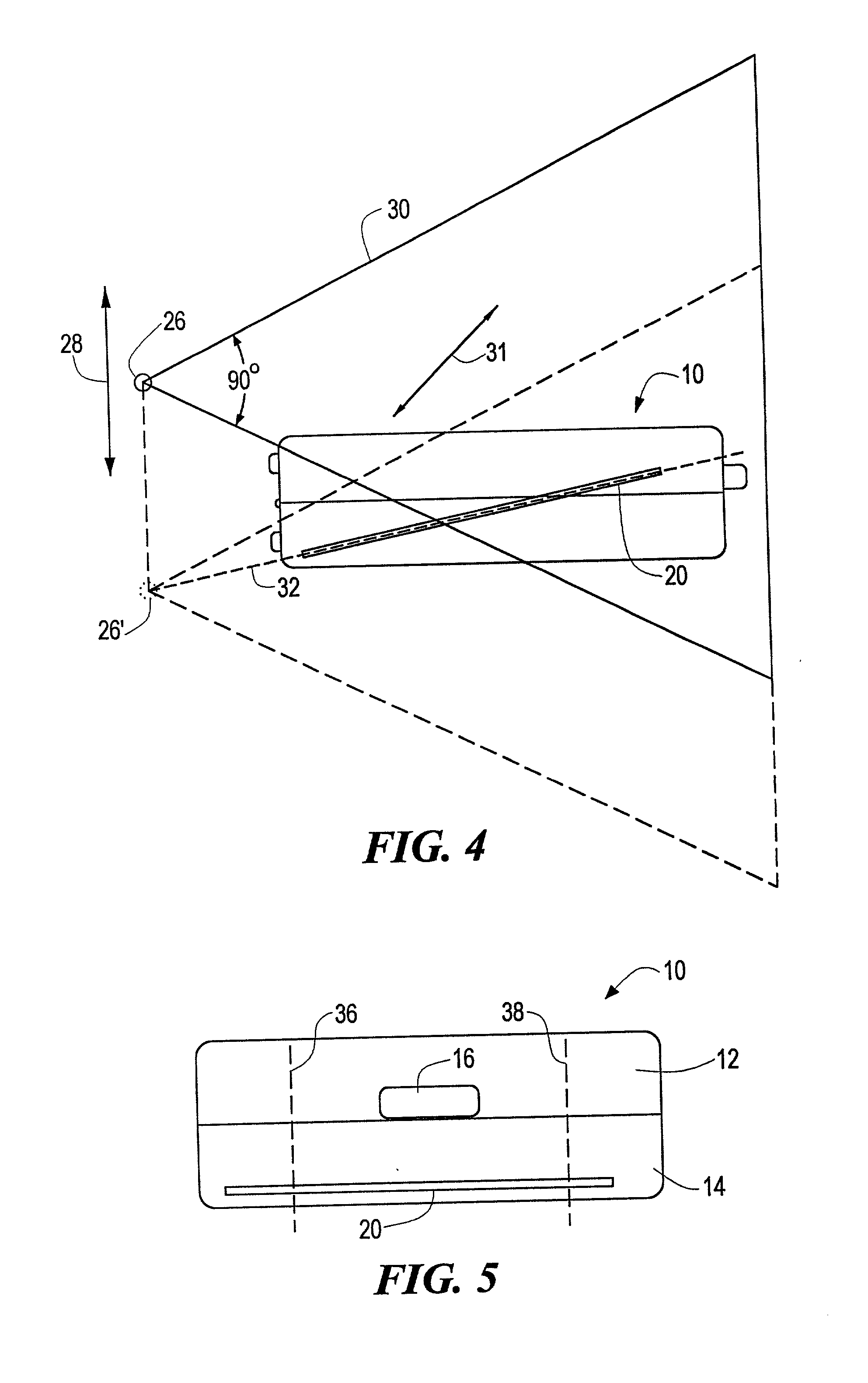
[0016] FIG. 4 is a view similar to FIGS. 1-3 in which the X-ray source is moved to align at some point the X-ray beam with the sheet, according to this invention;

[0017] FIG. 5 is a view similar to FIGS. 1-4 illustrating the spacing between scans to ensure interception of a sheet material;

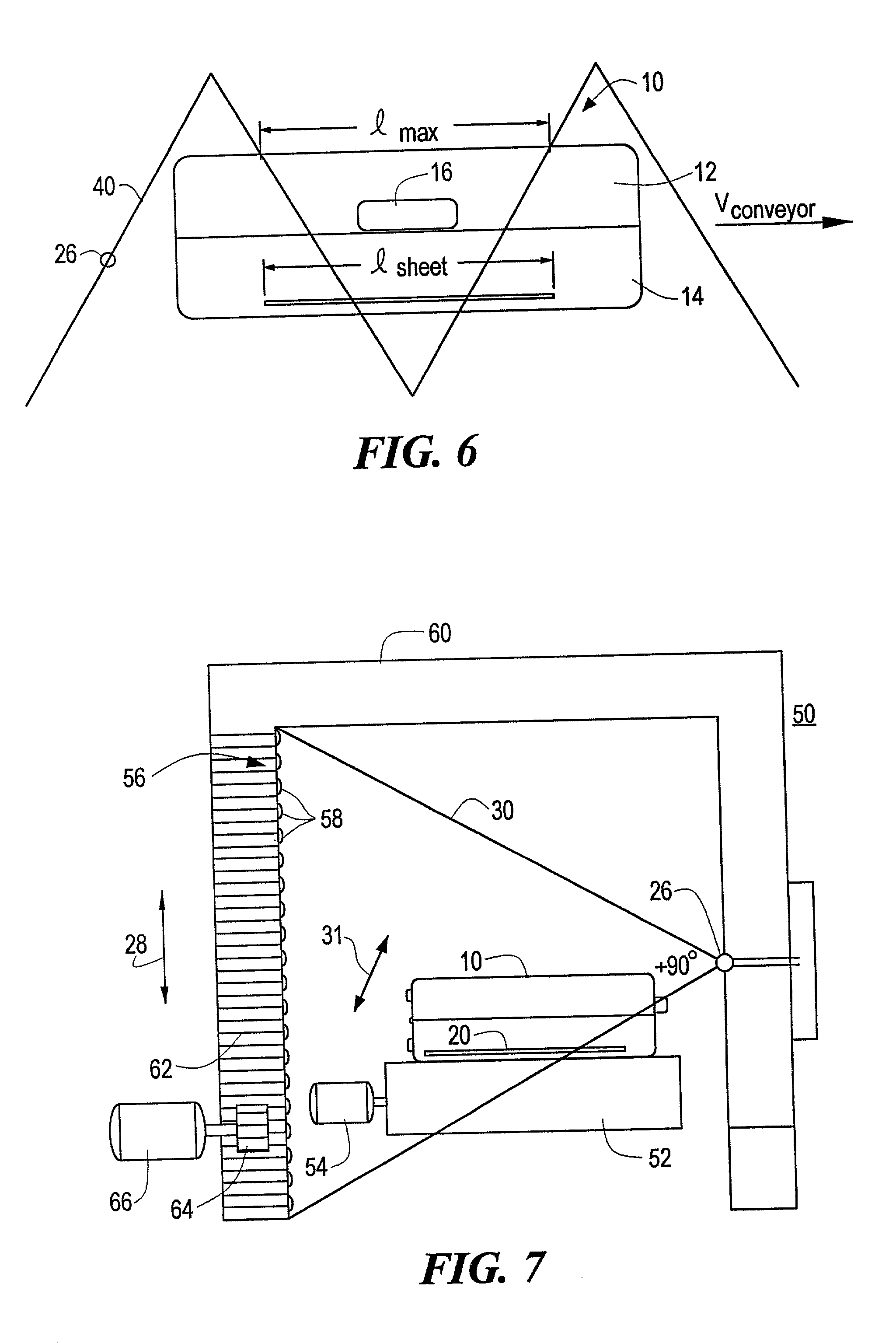
[0018] FIG. 6 is a view similar to FIGS. 1-5 ill...


PUM


Abstract

A detection system for detecting sheets of material includes a device for moving along a path a container which can harbor a sheet of material sought to be detected; an X-ray scanner having a beam for scanning across the path of the container through a predetermined angle and a device for moving the scanner to shift the origin of the scanning beam to align during at least a portion of the scan the scanning beam with the sheet for producing a high projected density contrasted with its surroundings.

Description

[0001] This invention relates to a detection system for detecting thin sheets of material, and more particular to a system for detecting sheets of organic material including contraband materials such as drugs and explosives.BACKGROUND OF INVENTION[0002] There are a number of different techniques for detecting objects in closed containers such as suitcases and boxes carried by airplanes which involve conveying the suitcases past an X-ray scanner. In particular, contraband such as drugs or explosive materials are sought to be detected by discerning their densities and / or atomic number using dual energy approaches. The dual energy atomic number approach relies on the fact that when an X-ray beam strikes material the energy of the beam is diminished either because of absorption (the photoelectric effect pe) or because of scattering (the Compton scattering effect .mu..sub.cs) and that the probability of the photoelectric effect, .mu..sub.pe, changes markedly with increased energy while t...

Claims


Application Information

Patent Timeline
IPC IPC(8): G01N23/04G01V5/00
CPCG01N23/04G01V5/0016G01V5/0041
Inventor BJORKHOLM, PAUL J.
Owner L3 COMMUNICATIONS SECURITY & DETECTION SYSTEMS CORPORATION
Why Eureka
Try Eureka